Multi-functional filter

A filter and function block technology, applied in the field of multi-function filters, can solve the problems that it can only be used for or condensate filters, and cannot be converted.

Active Publication Date: 2009-09-09
ULTRAFILTER INT
View PDF2 Cites 1 Cited by
  • Summary
  • Abstract
  • Description
  • Claims
  • Application Information

AI Technical Summary

Problems solved by technology

[0006] Although a change of function is not often required during filter operation, it has the disadvantage that filters with differential pressure indicators and / or condensate drains are in each case designed for one flow direction; therefore, the filter Can only be used with either condensation filters (flow direction from inside to outside) or dust filters, not interchangeable

Method used


Image

  • Multi-functional filter
  • Multi-functional filter
  • Multi-functional filter

Examples


Embodiment Construction

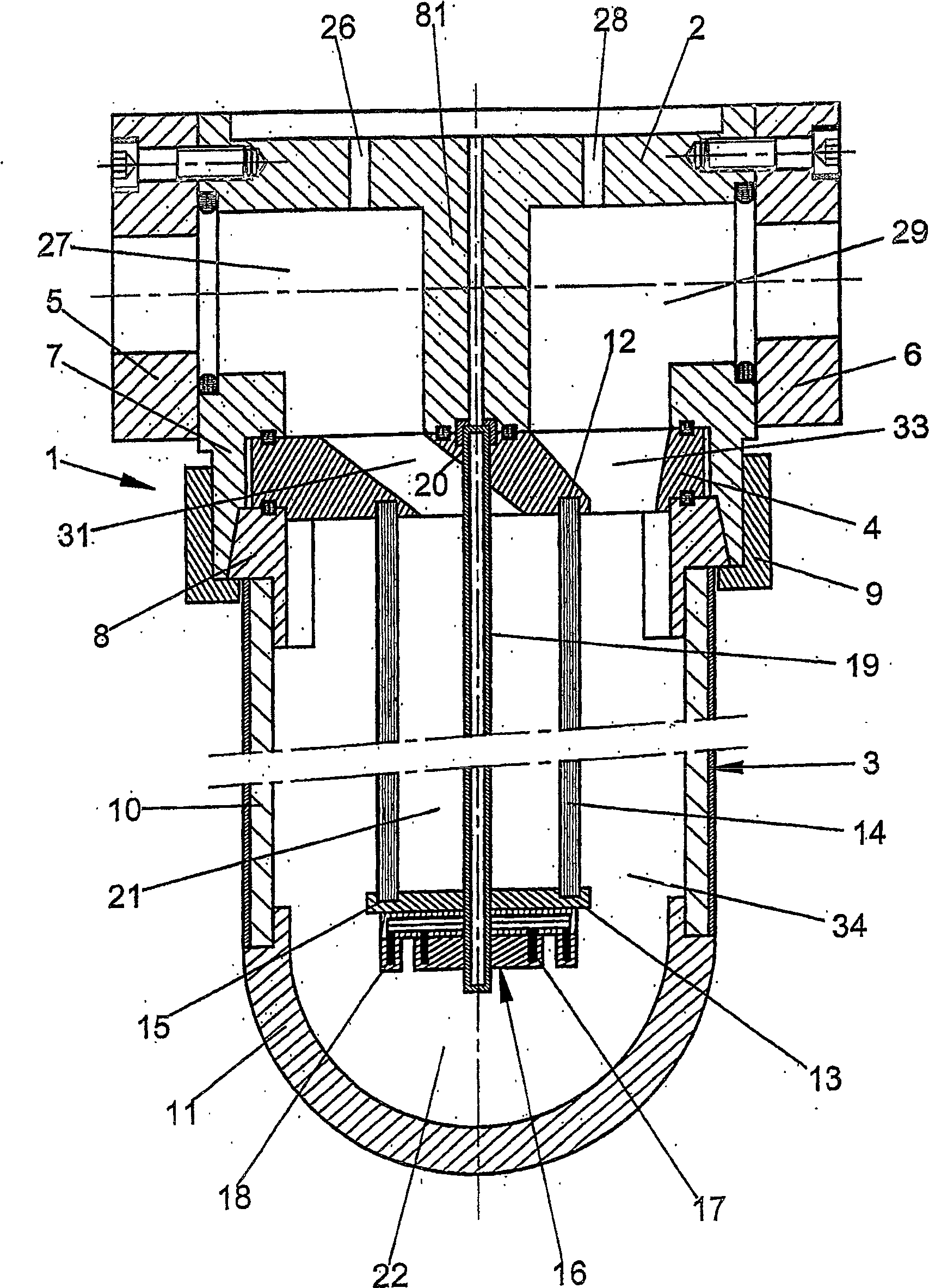
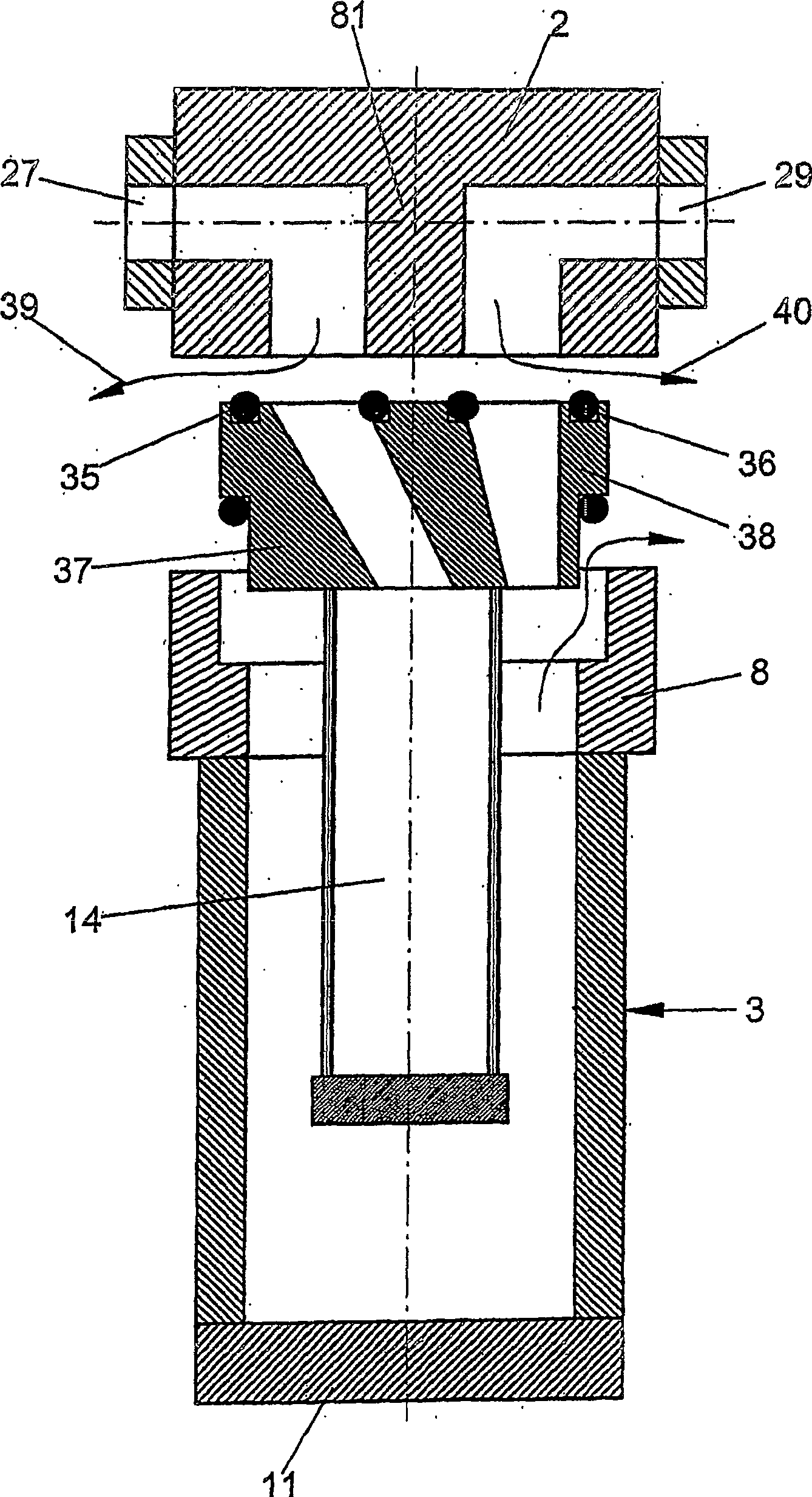
[0033] The shown filter 1 comprises a top 2 and a bottom 3 between which a connecting flange 4 is arranged. The top 2 has two connection adapters 5 , 6 via which the filter 1 can be introduced, for example, into a compressed air line (not shown). The loosely inserted connecting flange 4 is clamped by means of a connecting nut 9 between an inner ring 7 of the top 2 and a connecting ring 8 of the housing. The connecting ring 8 is fixedly connected to a cylindrical central part 10 of the housing, and the central part 10 is connected to a bottom cover 11 .

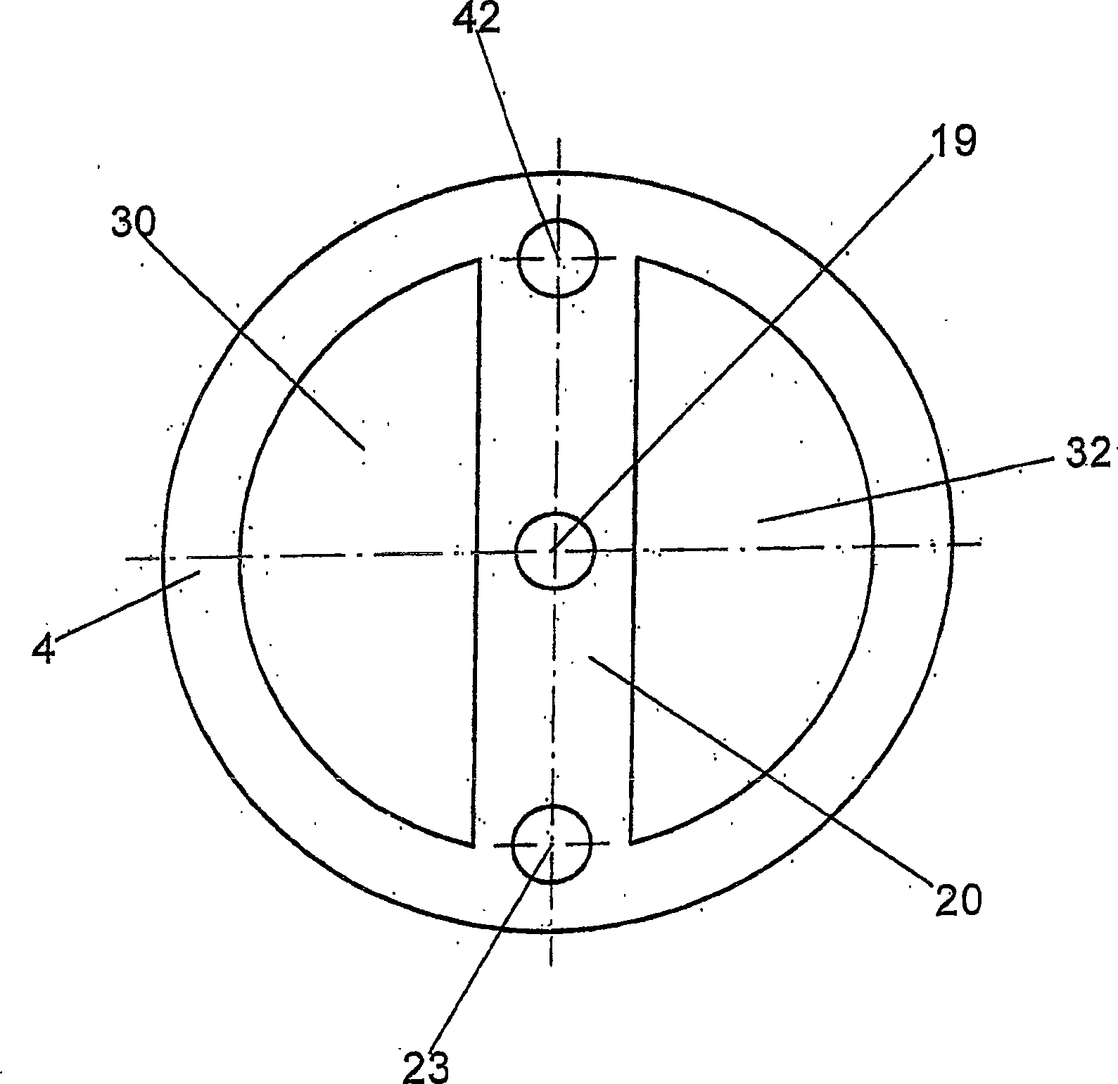
[0034] The upper edge of the hollow cylindrical filter element 14 , which is closed at the bottom by a cover 13 , is clamped in a groove 12 in the connecting flange 4 in a sealing or adhesive manner. The cover 13 likewise has a circumferential groove 15 into which the lower edge of the filter element 14 is glued or clamped. Cover 13 has a capacitive level sensor 16 with two ring electrodes 17 , 18 . A condensation pipe 19 e...


PUM


Abstract

A multi-functional filter has an upper section (2) that is separated from a lower section (3) by a twist-flange (4) with two kidney-shaped apertures separated by a cross-piece (20). The direction of gas flow through the filter is reversed by twisting the flange. The flange is clamped between the housing upper section and a secondary ring (8) with an O-ring seal. The flange can rotate with respect to the housing upper section, and is fixed to the filter insert (14).

Description

technical field [0001] The present invention relates to a multifunctional filter and claims priority from German patent application 103 09428.8-23, the text of which is hereby incorporated by reference. Background technique [0002] Compressed gas and especially compressed air systems require filters to separate out solid and liquid foreign matter such as dirty particles, condensate and oil mixed into the gas stream. [0003] Conventional air compression filters generally include a two-part housing having a top and a bottom that are either threaded to each other or connected to each other by a coupling nut or a bayonet piece. The housing top usually has an inflow channel and an outflow channel on directly opposite sides. The inflow channel is open either centrally screwed or bonded into a hollow cylindrical filter element in the top, or into the annular space between the filter element and the housing. Correspondingly, the outflow channel leads either to the outside of the...

Claims


Application Information

Patent Timeline
Patent Type & Authority Patents(China)
IPC IPC(8): B01D46/42B01D53/26B01D46/24B01D45/18B01D46/00B01D46/46
CPCB01D2273/14B01D46/46B01D46/0031B01D46/24B01D45/18B01D2265/05B01D46/42B01D53/26
Inventor H-M·舒斯特K·艾默
Owner ULTRAFILTER INT
Why Eureka
Try Eureka