
Burr removing machine tool

A deburring and machine tool technology, which is applied to grinding machines, machine tools suitable for grinding workpiece edges, metal processing equipment, etc., can solve the problem that deburring machine tools are not suitable for fine parts deburring, and achieve simple and practical processing methods and simple operation Convenience and less investment

Inactive Publication Date: 2009-09-09
SHANXI DATONG GEAR GROUP
View PDF10 Cites 0 Cited by
  • Summary
  • Abstract
  • Description
  • Claims
  • Application Information

AI Technical Summary

Problems solved by technology

[0006] In order to solve the problem that the deburring machine tool in the prior art is not suitable for deburring fine parts, the present invention provides a new type of deburring machine tool

Method used


Image

  • Burr removing machine tool
  • Burr removing machine tool

Examples


Embodiment Construction

[0023] The specific embodiments of the present invention will be further described in conjunction with the accompanying drawings, and the embodiments are used to illustrate the present invention, but not to limit it in any way.

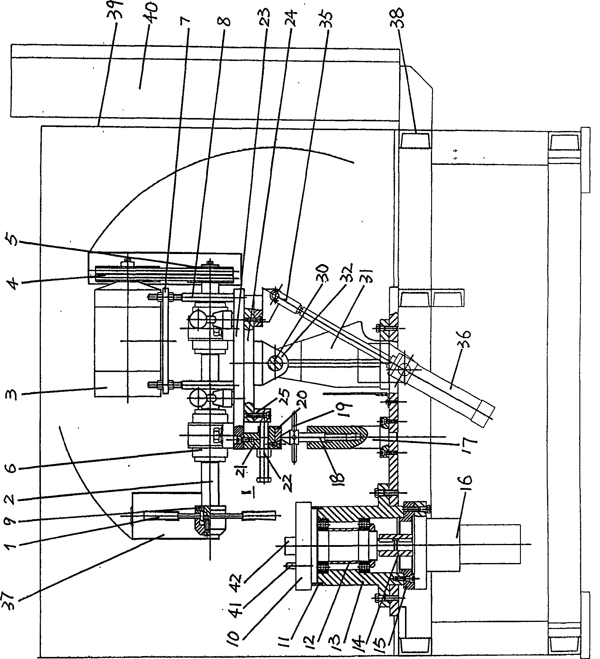
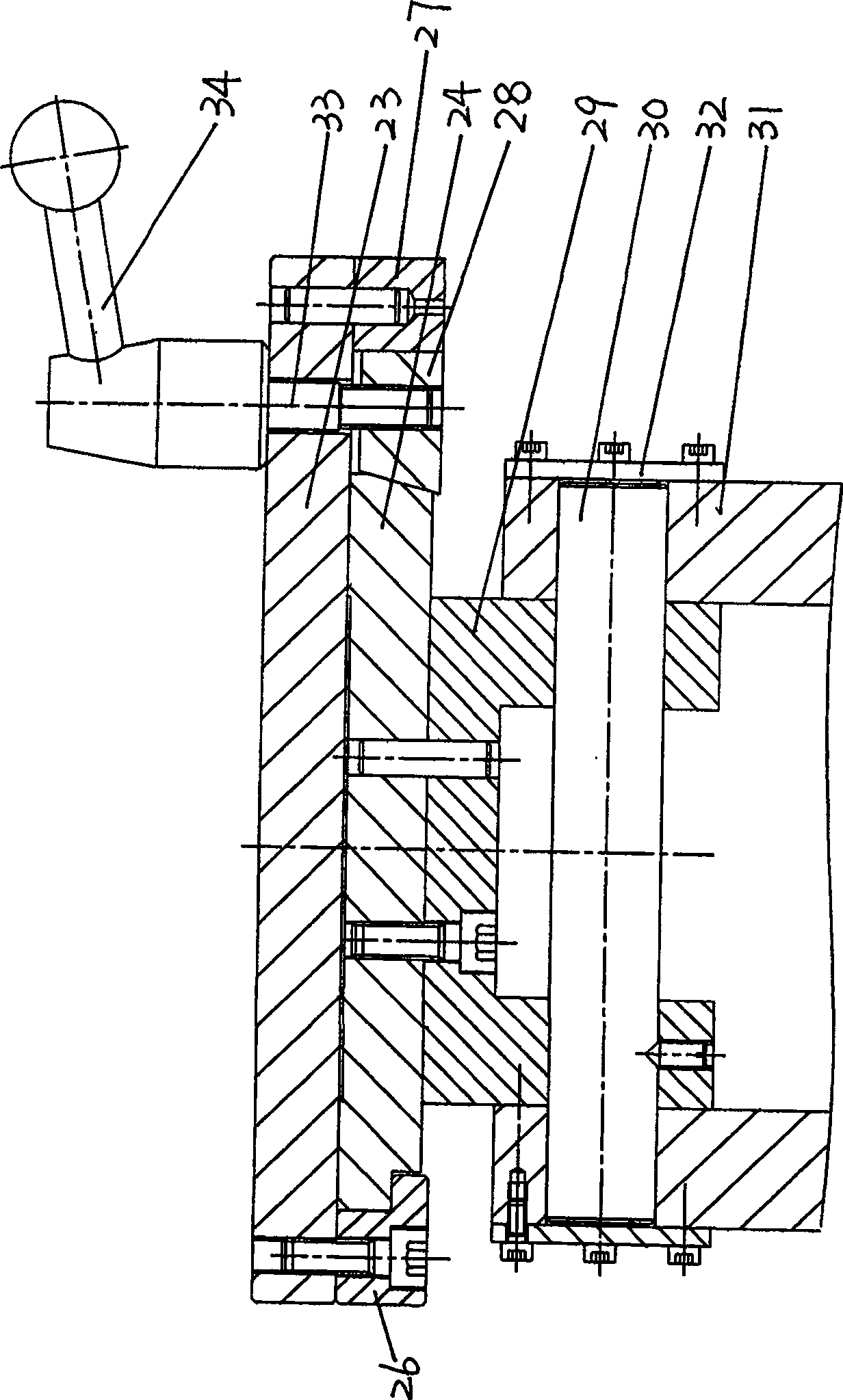
[0024] The deburring machine tool includes a deburring tool, a workpiece table, and a driving device. The deburring tool is a wire wheel 1, and the wire wheel 1 is connected to the driving device through a wire wheel shaft 2. The wire wheel shaft 2 is installed on the base plate 24, and the bottom of the base plate 24 Connect hydraulic oil cylinder 36; Described workpiece platform is the rotation workpiece platform.

[0025] The upper part of the base plate 24 is provided with a sliding plate 23, and the base plate 24 is installed on the base frame 31 through a rotary bracket 29. The rotary bracket 29 and the base frame 31 are connected by a rotating shaft 30, and a height adjuster is arranged between the base frame 31 and the rotation table. The top ...


PUM


Abstract

The invention belongs to the technical field of deburring machine tools and solves the problem that the deburring machine tools in the prior art are not suitable for deburring fine parts. The deburring machine tool includes a deburring tool, a workpiece table, and a driving device, and is characterized in that the wire wheel of the deburring tool is connected to the driving device through a wire wheel shaft, and the wire wheel shaft is installed on a base plate, and the bottom of the base plate is connected to a hydraulic oil cylinder; The workpiece table is a self-rotating workpiece table. The beneficial effects of the present invention are as follows: the processing method is simple and practical, which can save a lot of manpower; the operation is simple and convenient, and PC control is adopted, and the operation only needs to be up and down the workpiece, and the switch can be started; the processing efficiency is high, and it takes about 10-20 hours to process one end face. seconds; low cost, a wire wheel can process 5000-10000 workpieces; less investment, simple machine tool structure, about 4 months to produce a machine tool.

Description

technical field [0001] The invention belongs to the technical field of deburring machine tools. Background technique [0002] At present, the methods of deburring machine include: knife scraping, hammering and flame removal, etc., with knife scraping and hammering being the majority. [0003] The tool scraping type is divided into fixed slab and mobile slab. Its working principle is to raise the overall tool so that it is close to the head and tail of the slab, and remove the slab by relative movement between the slab and the tool. glitch. The original scraper-type deburring machine has a complex structure, takes up a lot of space, and has a high maintenance rate for equipment. [0004] The hammer-knife deburring machine uses a set of high-speed rotating hammer knives to remove the burrs from the head and tail of the billet. In this way, the lifting stroke of the hammer knife is fixed. When the head and tail of the slab are upturned or bent down, the burr removal rate wil...

Claims


Application Information

Patent Timeline
Patent Type & Authority Patents(China)
IPC IPC(8): B24B9/04
Inventor 孙国马明仁李青王祝山原鑫
Owner SHANXI DATONG GEAR GROUP
Learn More