

Device for drawing in veneer strips
A technology of plywood and equipment, which is applied in the jointing of wooden veneers, wood processing equipment, manufacturing tools, etc., can solve the problems of expensiveness, and achieve the effect of reasonable manufacturing, simple cost, and shortened cycle time
- Summary
- Abstract
- Description
- Claims
- Application Information
AI Technical Summary
Problems solved by technology
Method used
Image

Examples
Embodiment Construction
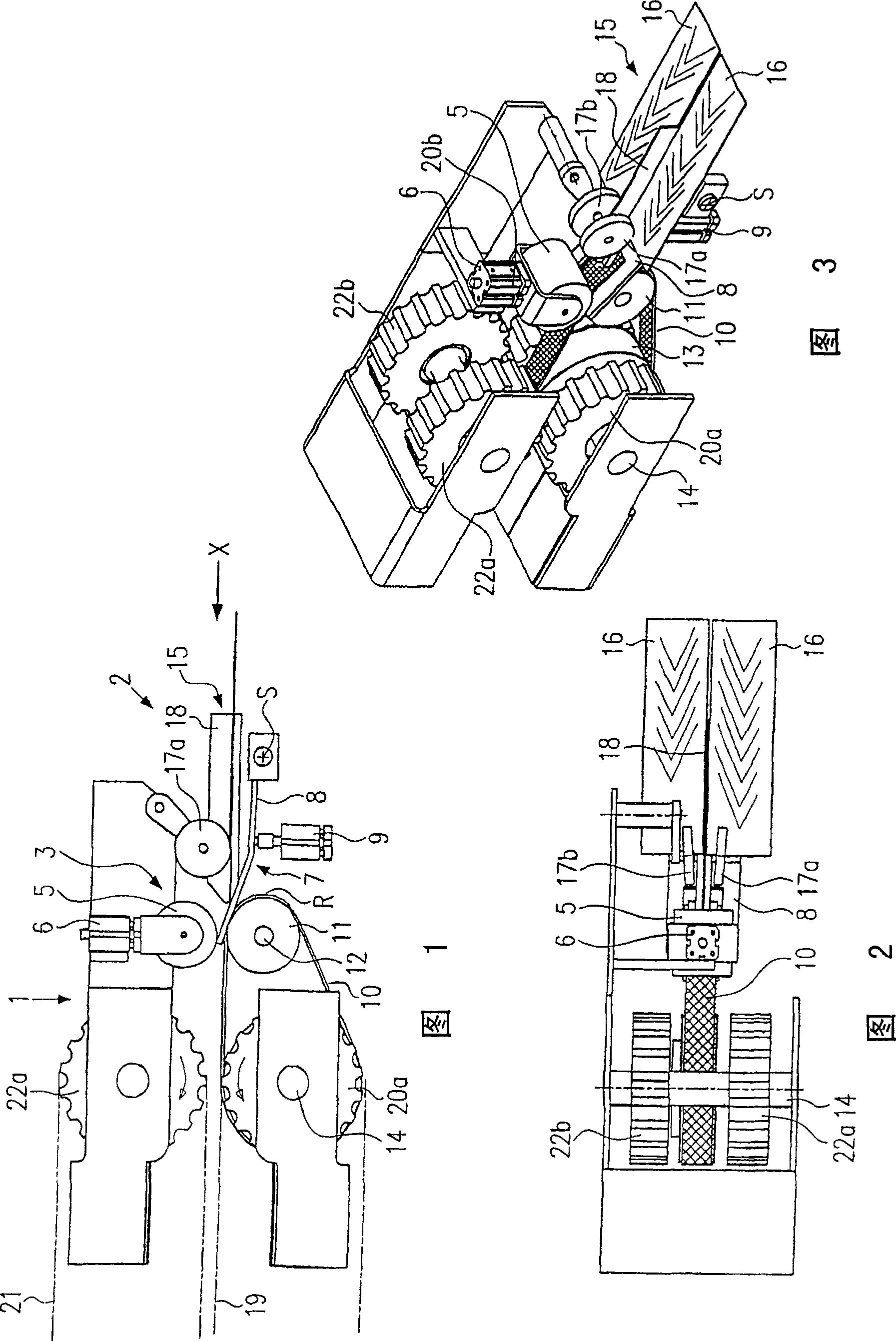
[0043] The plywood combining machine 1 according to the first structure will be described schematically and in consideration of its functions below with reference to FIGS. 1 to 6 . For better illustration, the plywood assembly machine 1 is only partially shown here. The veneer assembly machine 1 comprises, in a known manner, a conveyor device with a lower conveyor chain 19 and an upper conveyor chain 21 . The lower transmission chain 19 is driven in the direction of the arrow ( FIG. 1 ) via the shaft 14 and the gears 20a, 20b. The upper transmission chain 21 is driven in the direction of the arrow ( FIG. 1 ) via the shaft 12 and the gears 22a, 22b. Between the two conveyor chains 19 , 21 at least two side-by-side veneer strips are conveyed in a known manner to a heating device (not shown) in order to join the two veneer strips to each other.
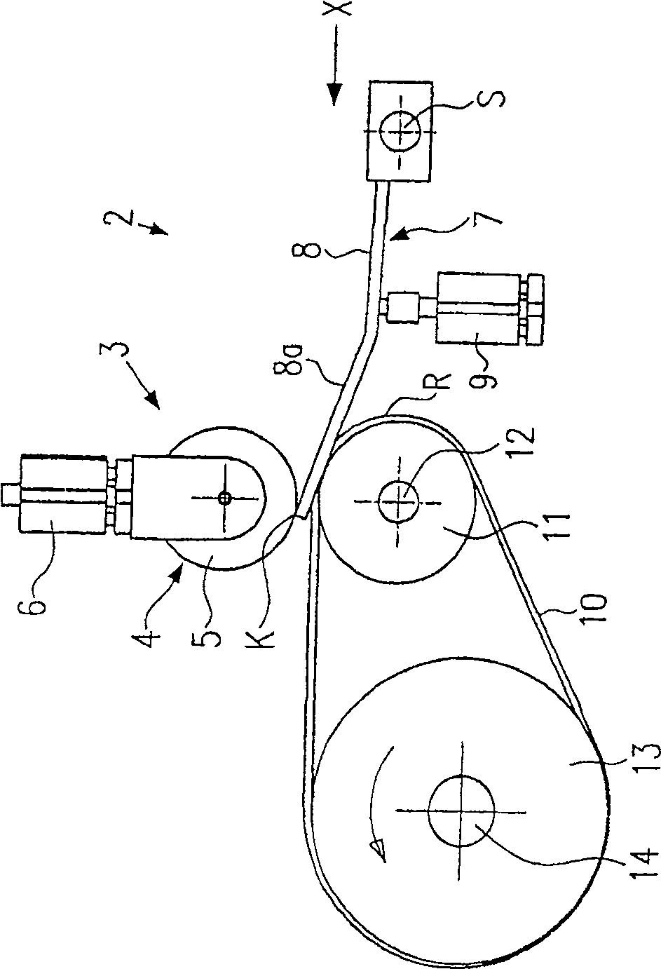
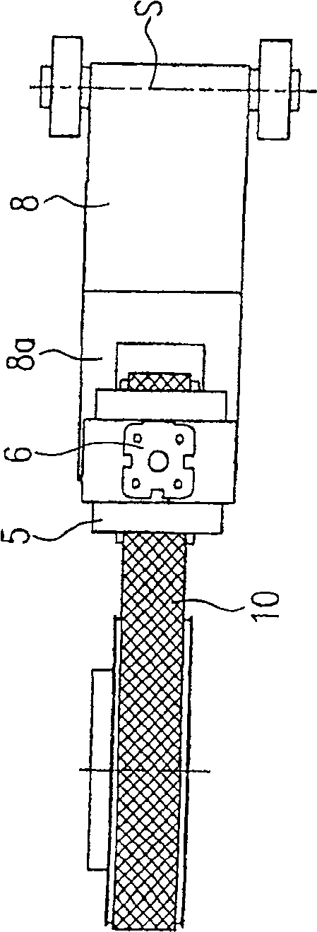
[0044] The plywood combination machine 1 also includes an input device 2, which is Figure 4 to Figure 6 shown in detail. The input...
PUM
 Abstract
Description
Claims
Application Information