Photocatalysis separation film performance test device and its test method
A photocatalytic separation membrane and testing device technology, which is applied in the field of photocatalytic separation membrane performance testing devices, can solve the problems of inability to test the performance of photocatalytic separation membranes, real-time online evaluation, complicated operation steps, etc., and achieve a scientific and feasible test method , The measured data is true and reliable, and the effect of expanding the light receiving range
- Summary
- Abstract
- Description
- Claims
- Application Information
AI Technical Summary
Problems solved by technology
Method used
Image
Examples
Embodiment 1
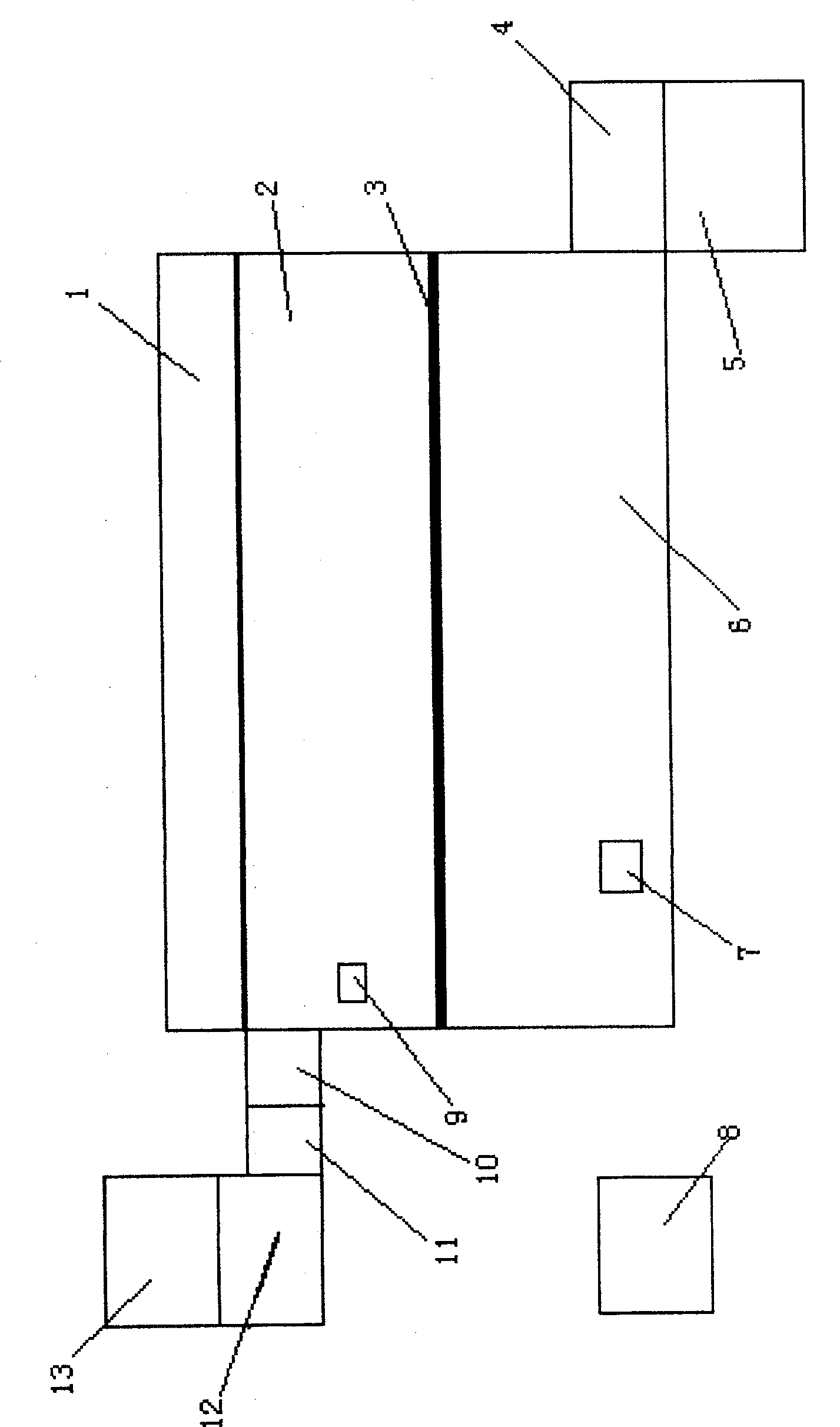
[0016] Embodiment 1: Complete the test in sequence according to the following steps: a) According to the purpose of testing the activity of the titanium dioxide photocatalytic separation membrane to degrade the liquid phase methylene blue, after preparing a 20 μmol / L methylene blue solution, place it in the container of the test object. b) The detector is selected as an ultraviolet-visible spectrophotometer, which is used to test the concentration of the methylene blue solution after the reaction. c) installing the photocatalytic separation membrane to be tested between the connected container of the degraded substance and the reactant container, and isolating them. Confirm that the light source is ultraviolet light, its wavelength is selected as 365nm, and the photon flux is selected as 6.94×10 per second -7 Mole photons, the ultraviolet light source is installed on one side of the container of the to-be-degraded product, and is arranged in parallel with the photocatalytic se...
Embodiment 2
[0017] Embodiment 2: Complete the test in sequence according to the following steps: a) According to the purpose of testing the activity of the titanium dioxide photocatalytic separation membrane to degrade liquid phase phenol, prepare a 20 mg / L phenol solution and place it in the sample container. b) The detector is selected as an ultraviolet-visible spectrophotometer, which is used to test the concentration of the phenol solution after the reaction. c) installing the photocatalytic separation membrane to be tested between the connected container of the degraded substance and the reactant container, and isolating them. Determine that the light source is ultraviolet light, its wavelength is selected as 254nm, and the photon flux is selected as 8.02×10 per second -7 Mole photons, the ultraviolet light source is installed on one side of the container of the to-be-degraded product, and is arranged in parallel with the photocatalytic separation membrane. d) According to the 0.5m ...
Embodiment 3
[0018] Example 3: The test was completed in sequence according to the following steps: a) According to the purpose of testing the activity of the titanium dioxide photocatalytic separation membrane to degrade formaldehyde in the gas phase, 5 μmol / L of formaldehyde gas was prepared and placed in the container of the test object. b) The detector is selected as a special gas detector for formaldehyde, which is used to test the concentration of formaldehyde gas after the reaction. c) installing the photocatalytic separation membrane to be tested between the connected container of the degraded substance and the reactant container, and isolating them. Determine that the light source is ultraviolet light, its wavelength is selected as 254nm, and the photon flux is selected as 6.94×10 per second -7 Mole photons, the ultraviolet light source is installed on one side of the container of the to-be-degraded product, and is arranged in parallel with the photocatalytic separation membrane. ...
PUM
| Property | Measurement | Unit |
|---|---|---|
| wavelength | aaaaa | aaaaa |
| adsorption capacity | aaaaa | aaaaa |
| adsorption capacity | aaaaa | aaaaa |
Abstract
Description
Claims
Application Information
 - R&D
- Intellectual Property
- Life Sciences
- Materials
- Tech Scout
- Unparalleled Data Quality
- Higher Quality Content
- 60% Fewer Hallucinations
Browse by: Latest US Patents, China's latest patents, Technical Efficacy Thesaurus, Application Domain, Technology Topic, Popular Technical Reports.
© 2025 PatSnap. All rights reserved.Legal|Privacy policy|Modern Slavery Act Transparency Statement|Sitemap|About US| Contact US: help@patsnap.com


