Forward switching method and router architecture based on the partial forward streamline switching

A router and flow technology, applied in data switching networks, transmission systems, digital transmission systems, etc., can solve the problem that the forwarding components are difficult to meet the storage requirements of large-scale routing and forwarding tables, and the centralized switching network is difficult to meet the port rate and port rate. The number, storage and logic device process development speed lag and other issues, to achieve the effect of good flexibility and scalability, elimination of segmentation and reorganization operations, and easy hardware implementation

Inactive Publication Date: 2009-10-07
NAT UNIV OF DEFENSE TECH
View PDF3 Cites 0 Cited by
  • Summary
  • Abstract
  • Description
  • Claims
  • Application Information

AI Technical Summary

Problems solved by technology

In this traditional router architecture, forwarding components are difficult to meet the storage requirements of large-scale routing and forwarding tables and the speed requirements of line-speed lookup tables, and the centralized switching network is difficult to meet the requirements of port speed and port number.
More importantly, under the inherent router architecture, the router's forwarding and switching capabilities are limited by the development speed of the storage and logic device technology level, which lags far behind the growth rate of the link rate.
At present, the research circles at home and abroad have also realized that it is difficult to meet the needs of future Internet development only by researching and improving the forwarding technology and switching technology of routers. It is necessary to seek innovation and breakthroughs in the router architecture, and to study it under the new router architecture. New message forwarding technology and switching technology, which is also a hot spot of research on router technology at home and abroad in recent years

Method used


Image

  • Forward switching method and router architecture based on the partial forward streamline switching
  • Forward switching method and router architecture based on the partial forward streamline switching
  • Forward switching method and router architecture based on the partial forward streamline switching

Examples


Embodiment Construction

[0042] The present invention will be described in further detail below in conjunction with the accompanying drawings and specific embodiments.

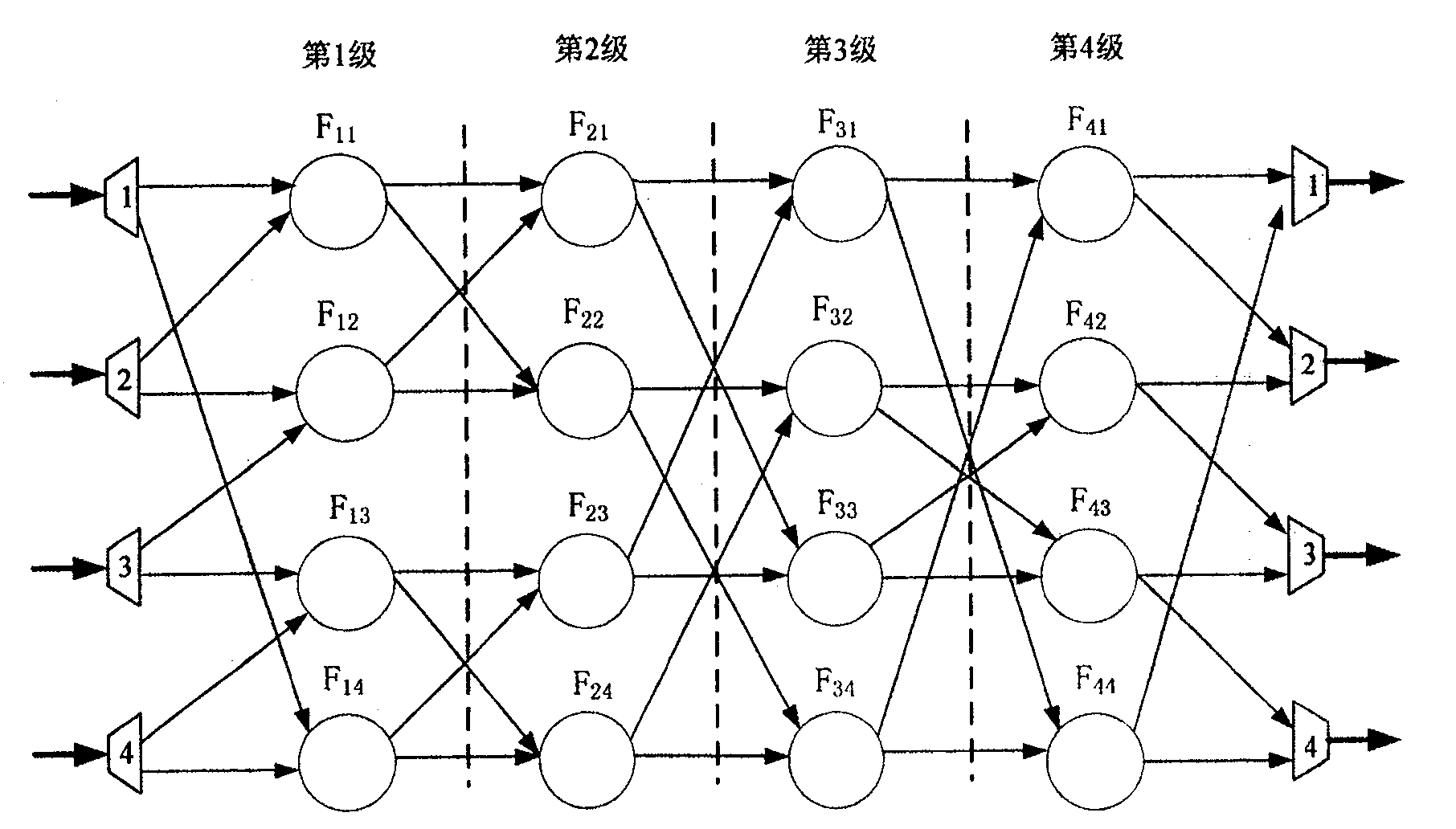
[0043] see figure 1 , figure 2 , image 3 and Figure 4 As shown, the router architecture based on partial forwarding pipeline switching of the present invention includes several forwarding and switching nodes with independent forwarding and switching functions, which can independently perform message forwarding and send the message to the correct output port according to the forwarding result. point, we call it forwarding and switching node FSN (Forwarding and Switching Node). Each forwarding and switching node only completes part of the forwarding operation of the message, and the final forwarding decision of the message cannot be obtained until the exit node; several forwarding and switching nodes form a multi-stage pipeline structure, and perform message forwarding and switching in a pipelined manner . Such as figure 1 As s...


PUM


Abstract

The disclosed transmission exchange router architecture comprises some independent nodes to transmit and exchange message. Wherein, every node completes partial operation for message transmission till obtaining the final transmission decision on the output node; some nodes form a multi-stage pipeline structure for executing operation. Wherein, the relative method comprises: decomposing route transmission table, mapping sub-tree to node, and determining the next node. This invention reduces requirement on single part, and improves whole performance.

Description

technical field [0001] The invention mainly relates to the design field of the router system structure, in particular to a forwarding switching method and a router system structure based on partial forwarding flow switching. Background technique [0002] With the continuous growth of the Internet link rate and the number of IP prefixes, higher and higher requirements are placed on the router, the core device of Internet interconnection. The new generation of high-performance routers is facing challenges in several aspects: the link rate is getting higher and higher, and it has developed from OC192 (10Gb / s) to OC768 (40Gb / s) and even OC3072 (160Gb / s); The number of prefixes in the routing table has reached 500,000 and continues to grow, and will reach 1 million in the near future; with the application of the IPv6 protocol, the prefix length in the routing table will increase from 32 bits to 128 bits. The above-mentioned development trend poses severe challenges to the forwa...

Claims


Application Information

Patent Timeline
Patent Type & Authority Patents(China)
IPC IPC(8): H04L12/56H04L12/721
Inventor 孙志刚戴艺管剑波时向泉陈一骄吕高峰
Owner NAT UNIV OF DEFENSE TECH
Why Eureka
Try Eureka