Disposable injector

A syringe and disposable technology, applied in the field of syringes, can solve the problems of complex structure, inability to directly accommodate the medicine cartridge 96, troubles in manufacture and use, etc.

Inactive Publication Date: 2009-10-28
许 明正 +2
View PDF9 Cites 0 Cited by
  • Summary
  • Abstract
  • Description
  • Claims
  • Application Information

AI Technical Summary

Problems solved by technology

[0005] 1. Generally speaking, the main purpose of using a syringe containing liquid medicine is to simplify the process of pre-extracting the liquid medicine in the medicine tank with the injection syringe in clinical operations, and then injecting it. In addition to simplifying the medical operation procedures, It is also possible to avoid situations such as contamination or needle sticking in the process of preparing medicine such as extracting medicinal liquid with a syringe, but the cartridge 96 of the syringe 9 cannot be directly accommodated in the syringe 91, otherwise the needle will body 94 pierces the situation of the cartridge 96 closure 963, therefore, the cartridge 96 must be packaged separately from the syringe 9, and when used, the cartridge 96 is combined with the push rod 97 before being assembled into the cartridge 96. In the syringe 91, obviously, the syringe 9 just changes the action of extracting the medicinal liquid into the action of assembling it into the cartridge 96, and does not really achieve the simplification of the operation procedure of clinical medical injection drug treatment
[0006] 2. Since the needle body 94 and the needle seat 93 are retracted and hidden in the inner pipe section 971 of the push rod 97 after use, the positioning member 92 and the needle seat must be released synchronously before the elastic element 95 is activated. 93, the sealing member 963 and the cartridge 92, and the elastic body 98, the collar 99 and the cartridge 96, not only have more key components but also have a more complicated structure, thereby forming a problem in manufacturing and use. on the trouble
[0007] This shows that above-mentioned existing injector obviously still has inconvenience and defect in structure and use, and demands urgently further improving
In order to solve the above-mentioned problems, the relevant manufacturers have tried their best to find a solution, but no suitable design has been developed for a long time, and the general products do not have a suitable structure to solve the above-mentioned problems. This is obviously related. The problem that the industry is eager to solve

Method used


Image

  • Disposable injector
  • Disposable injector
  • Disposable injector

Examples


Embodiment Construction

[0075] In order to further explain the technical means and effects of the present invention to achieve the intended purpose of the invention, the specific implementation, structure, characteristics and effects of the disposable syringe proposed according to the present invention will be described below in conjunction with the accompanying drawings and preferred embodiments. The details are as follows.

[0076] Before the present invention is described in detail, it should be noted that in the following description, similar elements are denoted by the same reference numerals.

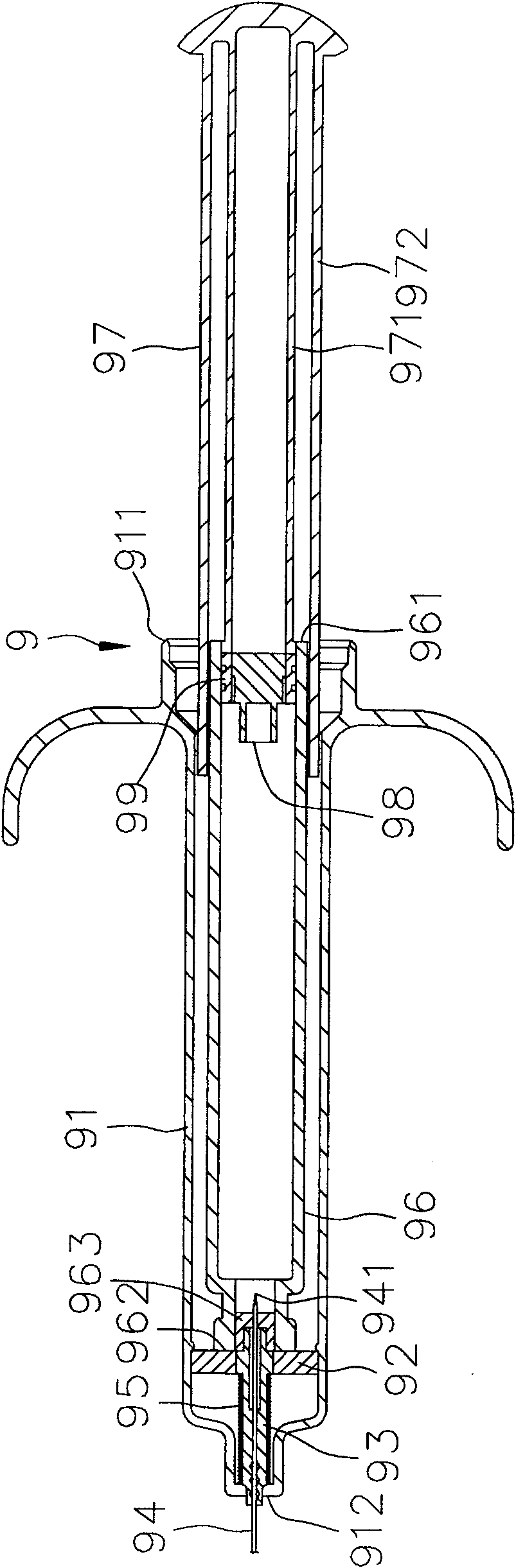
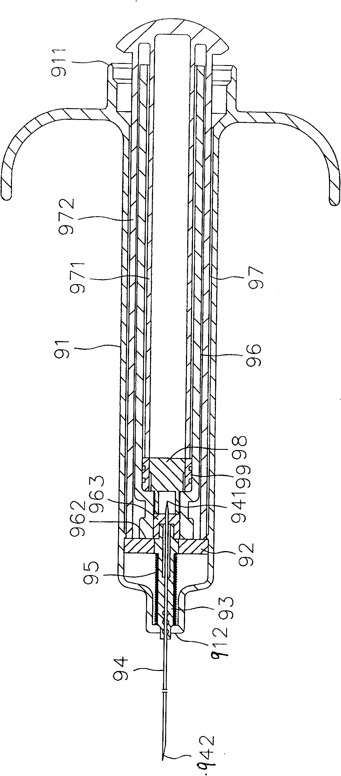
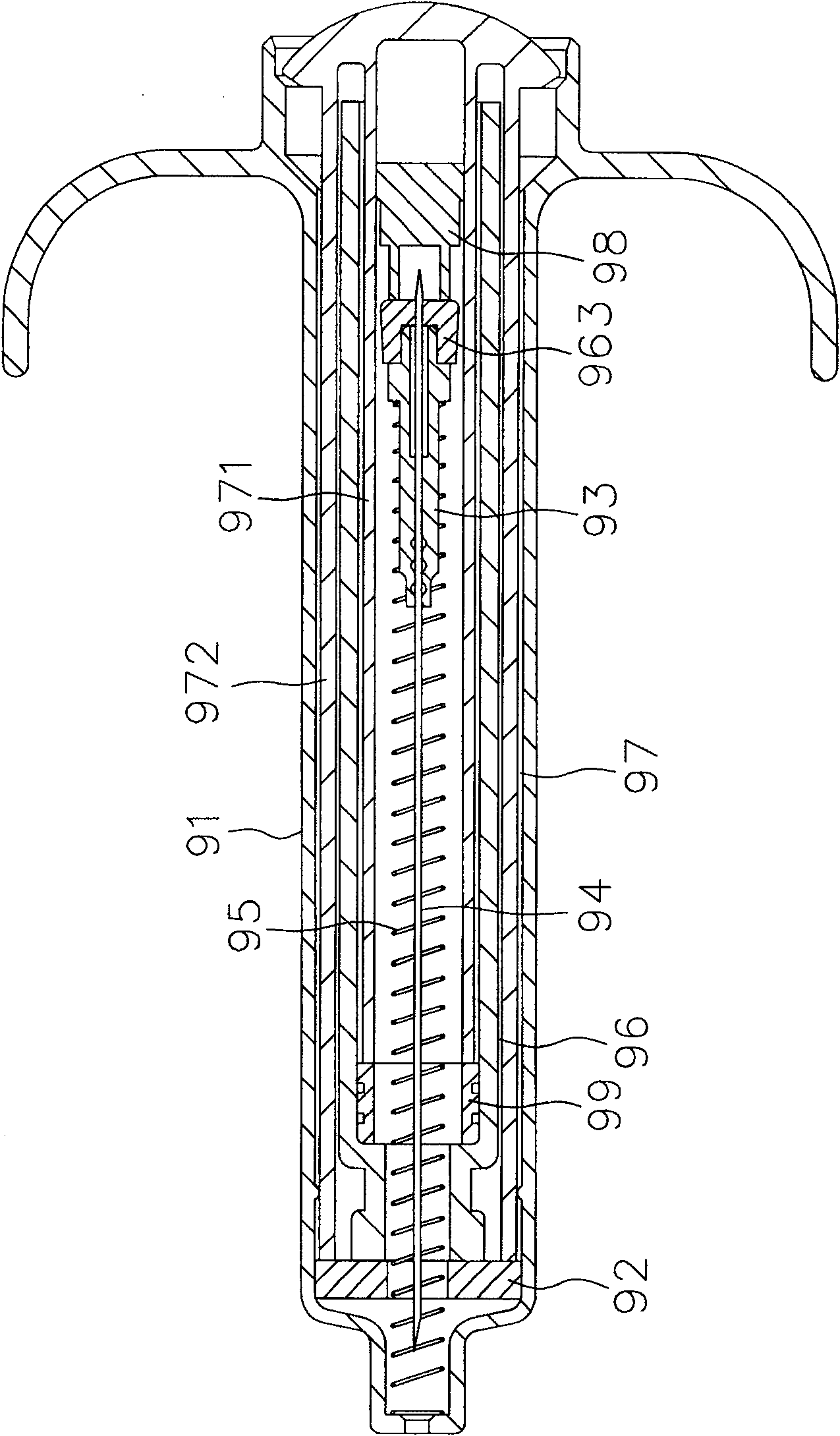
[0077] see Figure 4 , Figure 5 and Image 6 Shown are the disassembled sectional view, assembled sectional view and partially enlarged schematic view of the first preferred embodiment of the disposable syringe of the present invention. The first preferred embodiment of the disposable syringe of the present invention includes: a syringe 1, a needle set 2, a cartridge 3, a pusher 4, and a protective c...


PUM


Abstract

The invention relates to a disposable syringe, which includes a syringe, a needle set, a drug cartridge filled with medicinal liquid and displaceably accommodated in the syringe, and a device capable of pushing the medicinal liquid and the cartridge. One push mail. The needle set has a positioning member positioned in the syringe, a ring seat limited between the positioning member and an outlet end of the syringe, a needle body passing through the ring seat and out of the syringe, And an elastic element against the ring seat and the outlet end of the syringe. In this way, the pushing member can inject medicinal liquid during the pushing process, and at the end of the injection stroke, push the cartridge and push the positioning member to move toward the outlet end of the syringe, so as to release the positioning relationship with the ring seat and activate The elastic element makes the stretched elastic element push the ring seat, the needle body and the drug cartridge hidden in the syringe, and shrink the pushing member synchronously. The invention has the functions of simplifying the operation procedure of injection drug treatment in clinical medicine and improving the safety of injection operation.

Description

technical field [0001] The invention relates to a syringe, in particular to a disposable syringe which contains medicinal liquid in advance, can simplify the operation procedure of injecting medicine in clinical medicine, and can improve the safety and efficacy of injection operation. Background technique [0002] see figure 1 , figure 2 as shown, figure 1 It is a sectional view illustrating the case of U.S. Patent No. US6229055, figure 2 It is a sectional view illustrating the displacement of a push rod to the end of the injection stroke in the case of US Pat. No. 6,229,055. Taking the U.S. Patent No. US6229055 case as an example, the syringe 9 mainly includes a syringe 91, a positioning member 92, a needle seat 93, a needle body 94, an elastic element 95, a cartridge 96, a push rod 97, An elastic body 98 and a ring 99 . The syringe 91 has an inlet port 911 and an outlet port 912 opposite to each other. The positioning member 92 is detachably fastened in the syringe...

Claims


Application Information

Patent Timeline
Patent Type & Authority Patents(China)
IPC IPC(8): A61M5/178A61M5/31A61M5/50
Inventor 许明正黄明敏许沛扬
Owner 许 明正
Why Eureka
Try Eureka