Grinding dispersion device
A technology of grinding and dispersing and spraying head, which is applied in the direction of mixer with rotating stirring device, dissolving, grain processing, etc. It can solve the problems of large space occupation, loose structure and small particle size, so as to improve the efficiency of grinding and dispersing and reduce the amount of adhesion , strong coloring effect
- Summary
- Abstract
- Description
- Claims
- Application Information
AI Technical Summary
Problems solved by technology
Method used
Image
Examples
no. 1 example
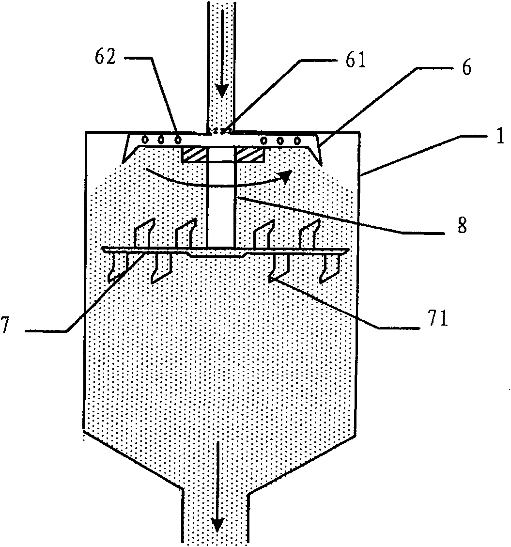
[0024] figure 1 It is a structural schematic diagram of the first embodiment of the present invention. Such as figure 1 As shown, the main structure of this embodiment includes an outer barrel 1, a spray head 6 and a stirring knife head 7 arranged in the outer barrel 1, wherein the spray head 6 is used to eject materials at high speed during high-speed rotation, which is convenient for high-viscosity materials The pulverizing and dispersing; the mixing knife head 7 is used to scrape the material attached to the inner wall of the outer barrel 1 during high-speed rotation, so as to mix the material in time and fully. Because the stirring cutter head 7 of this embodiment is arranged below the spray head 6, therefore, the stirring cutter head 7 can also fully stir and pulverize the material sprayed from the spray head 6 again during the high-speed rotation process, which is beneficial to Improve the efficiency of grinding and dispersing.
[0025] When this embodiment is in use,...
no. 2 example
[0031] This embodiment is a further application of the first embodiment of the present invention. On the basis of the technical solution of the first embodiment of the present invention, in order to increase the amount of grinding material in a single time and fully grind and disperse the material, the outer material cylinder can be connected to the grinding cylinder; on this basis, in order to further improve the grinding and dispersing efficiency, A gas booster for pressurizing high-viscosity materials can be added. Figure 4 It is a structural schematic diagram of the second embodiment of the present invention. Such as Figure 4 As shown, the difference between this embodiment and the first embodiment is that this embodiment also includes a material pipe 3, a grinding cylinder 2, a gas booster 4 and a rotating shaft 5, wherein:
[0032] The outer barrel 1 is used to increase the amount of dispersed material in a single grinding. The lower end of the outer barrel 1 is conn...
no. 3 example
[0040] On the basis of the technical solution of the second embodiment of the present invention, in order to make the structure of the present invention more concise and compact, the relative positions of the spray head and the stirring knife head arranged in the outer barrel can be adjusted.
[0041] Figure 5 It is a structural schematic diagram of the third embodiment of the present invention. Such as Figure 5 As shown, the difference between this embodiment and the second embodiment is that, in this embodiment, the stirring cutter head 7 is located directly above the spray head 6; the stirring cutter head is directly coaxially fixed on the rotating shaft 5, and can Driven to rotate at a high speed along the axis of the outer barrel 1; the stirring blade 71 on the outer edge of the stirring head 7 goes deep into the bottom of the spray head 6 to scrape off the material attached to the inner surface of the outer barrel.
[0042] In order to make the stirring blade under t...
PUM
 Abstract
Description
Claims
Application Information
 - R&D
- Intellectual Property
- Life Sciences
- Materials
- Tech Scout
- Unparalleled Data Quality
- Higher Quality Content
- 60% Fewer Hallucinations
Browse by: Latest US Patents, China's latest patents, Technical Efficacy Thesaurus, Application Domain, Technology Topic, Popular Technical Reports.
© 2025 PatSnap. All rights reserved.Legal|Privacy policy|Modern Slavery Act Transparency Statement|Sitemap|About US| Contact US: help@patsnap.com


