
Magnetic field-producing device

A technology for generating devices and magnetic fields, applied to measuring devices, magnets, magnetic objects, etc., can solve problems such as poor efficiency

Inactive Publication Date: 2009-11-04
PROTERIAL LTD
View PDF11 Cites 0 Cited by
  • Summary
  • Abstract
  • Description
  • Claims
  • Application Information

AI Technical Summary

Problems solved by technology

It is thought that these requirements can be met if two MRI apparatuses are used in parallel. However, in addition to the magnetic circuit part, the MRI apparatuses that have been put into practical use are equipped with many peripheral devices. Even if it is configured as a magnetic circuit, the efficiency is not good, and the overall size of the device will be increased. Therefore, the above-mentioned juxtaposed configuration has not been adopted in reality.

Method used


Image

  • Magnetic field-producing device
  • Magnetic field-producing device
  • Magnetic field-producing device

Examples


Embodiment Construction

[0034] Hereinafter, embodiments of the present invention will be described with reference to the drawings.

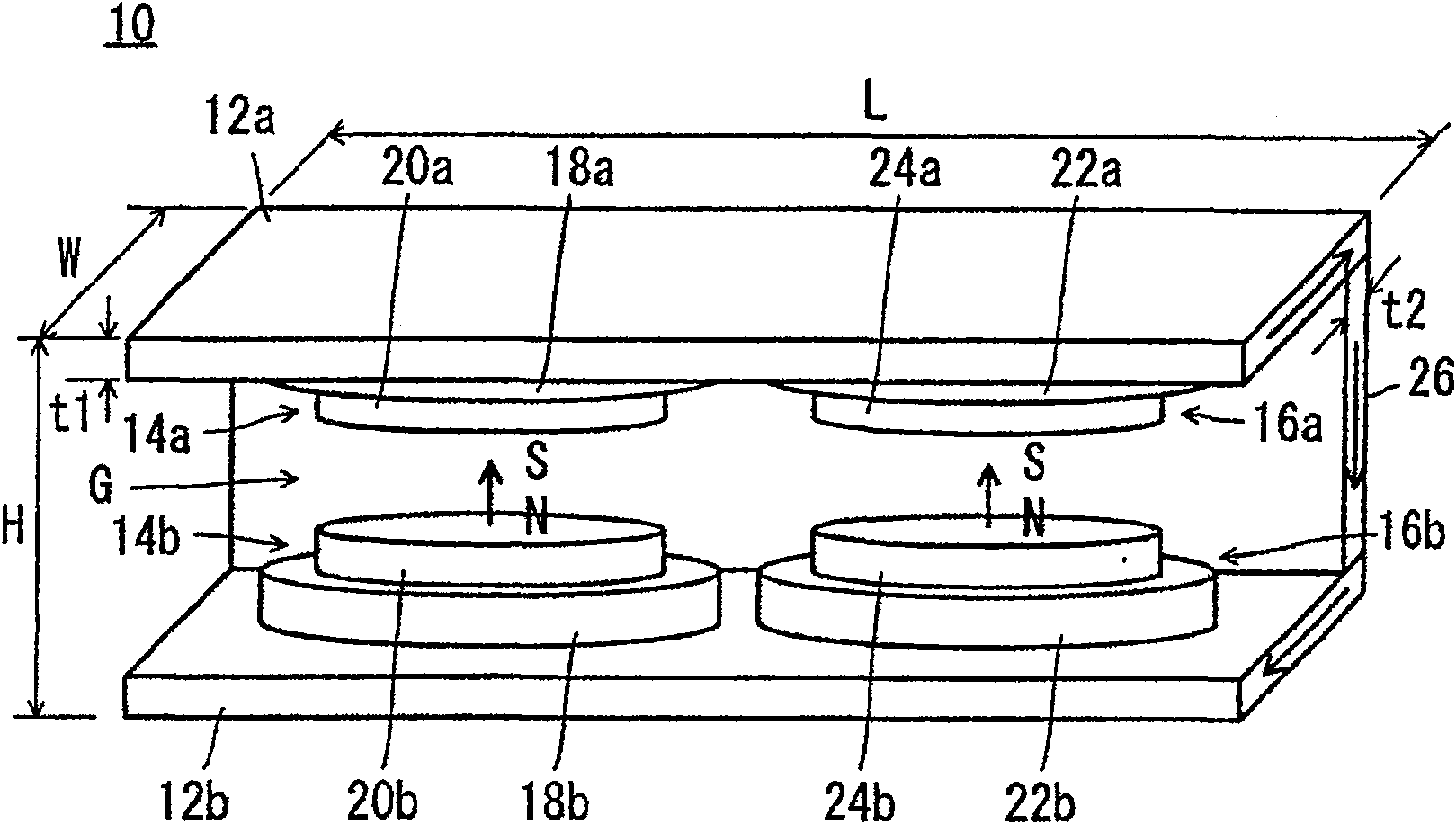
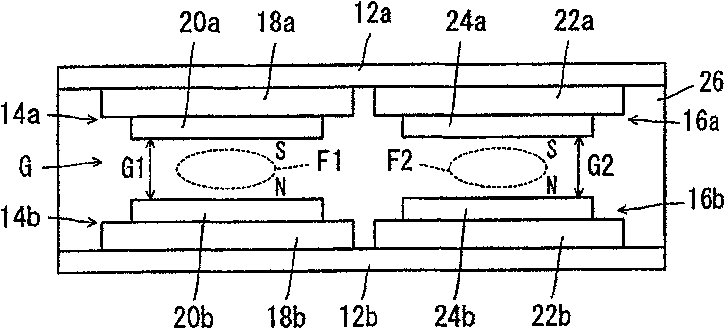
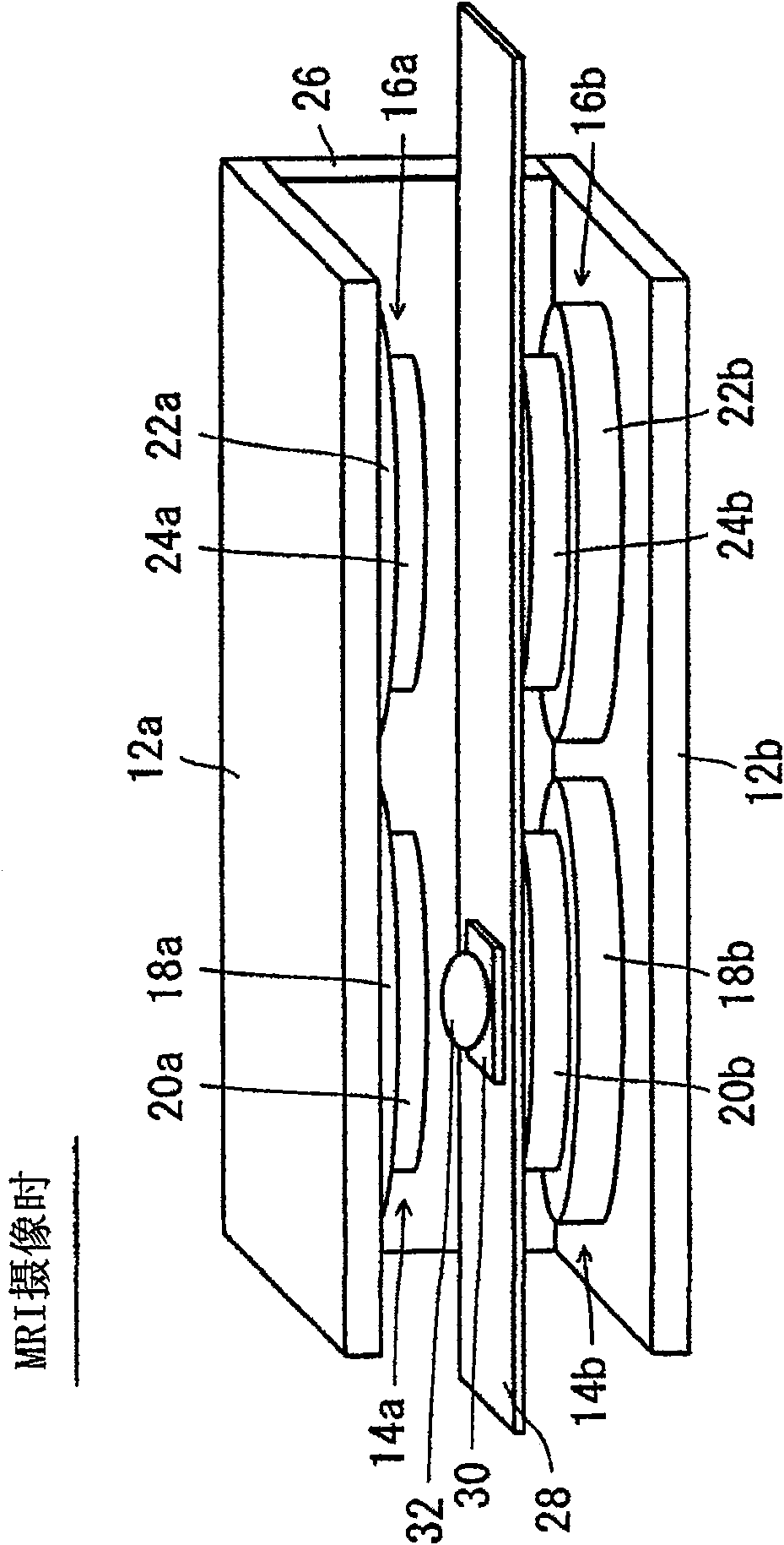
[0035] see figure 1 with figure 2 , The magnetic field generating device 10 according to one embodiment of the present invention is a permanent magnet type magnetic field generating device including a pair of plate-shaped yokes 12 a and 12 b arranged to face each other with a gap G formed.

[0036] Between the pair of plate-like yokes 12a and 12b, two pairs of opposing magnetic poles, that is, a pair of opposing magnetic poles 14a, 14b and a pair of opposing magnetic poles 16a, 16b are formed.

[0037] The pair of magnetic poles 14a, 14b each include permanent magnet groups 18a, 18b arranged on the opposing surfaces of the pair of plate-shaped yokes 12a, 12b. Magnetic pole pieces 20a, 20b are fixed to opposing surfaces of the permanent magnet groups 18a, 18b. Similarly, the pair of magnetic poles 16a, 16b each includes permanent magnet groups 22a, 22b arranged on th...


PUM


Abstract

The present invention provides a magnetic field generating device (10) capable of obtaining a uniform high magnetic field at multiple places. A magnetic field generating device (10) includes a pair of plate-shaped yokes (12a), (12b) arranged to face each other with a gap (G) formed. Between a pair of plate-shaped yokes (12a), (12b), a pair of opposing magnetic poles (14a), (14b) and a pair of opposing magnetic poles (16a), (16b) are provided. A pair of magnetic poles (14a), (14b) respectively include permanent magnet groups (18a), (18b) arranged on opposing surfaces of a pair of plate yokes (12a), (12b). Magnetic pole pieces (20a), (20b) are fixed to opposing surfaces of the permanent magnet groups (18a), (18b). A pair of magnetic poles (16a), (16b) includes permanent magnet groups (22a), (22b) arranged on opposing surfaces of the pair of plate yokes (12a), (12b), respectively. Magnetic pole pieces (24a), (24b) are fixed to opposing surfaces of the permanent magnet groups (22a), (22b). Magnetic field uniform spaces (F1), (F2) are respectively formed between the pole pieces (20a), (20b) and between (24a), (24b).

Description

technical field [0001] The present invention relates to a magnetic field generating device, and more particularly, to a permanent magnet type magnetic field generator that can be used in an MRI (Magnetic Resonance Imaging, magnetic resonance imaging) device or an ESR imaging (Electron SpinResonance, electron spin resonance imaging) device or a combination thereof. magnetic field generator. Background technique [0002] In order for MRI and ESR imaging to be imaged simultaneously, magnetic fields of different sizes are required. Generally speaking, MRI needs to use a high magnetic field above 0.2T, while ESR imaging needs to use a magnetic field that is less than half (eg, 0.04T). As such a device, a device that generates a magnetic field required for MRI and a magnetic field required for ESR imaging with a single electromagnet has been proposed in, for example, JP-A-9-299347. According to this method, the intensity of the resonant magnetic field for ESR imaging and the int...

Claims


Application Information

Patent Timeline
Patent Type & Authority Patents(China)
IPC IPC(8): A61B5/055G01R33/383H01F7/02
CPCH01F7/0278G01R33/383
Inventor 青木雅昭
Owner PROTERIAL LTD
Learn More