
High pressure pump for a fuel injection device of an internal combustion engine

一种燃料喷射装置、高压泵的技术,应用在用于内燃机的燃料喷射装置的高压泵领域,能够解决润滑特性恶化、不能保证高压泵寿命等问题,达到改善抗摩擦性的效果

Inactive Publication Date: 2009-11-04
ROBERT BOSCH GMBH
View PDF7 Cites 0 Cited by
  • Summary
  • Abstract
  • Description
  • Claims
  • Application Information

AI Technical Summary

Problems solved by technology

However, where the lubricating properties of the fuel deteriorate
Due to this, in some cases, it cannot be guaranteed that the high pressure pump has a sufficient life

Method used


Image

  • High pressure pump for a fuel injection device of an internal combustion engine
  • High pressure pump for a fuel injection device of an internal combustion engine
  • High pressure pump for a fuel injection device of an internal combustion engine

Examples


Embodiment Construction

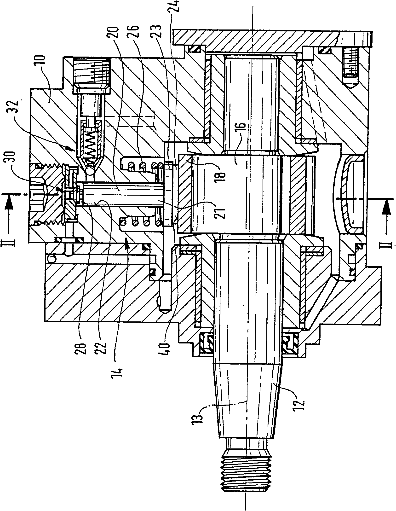
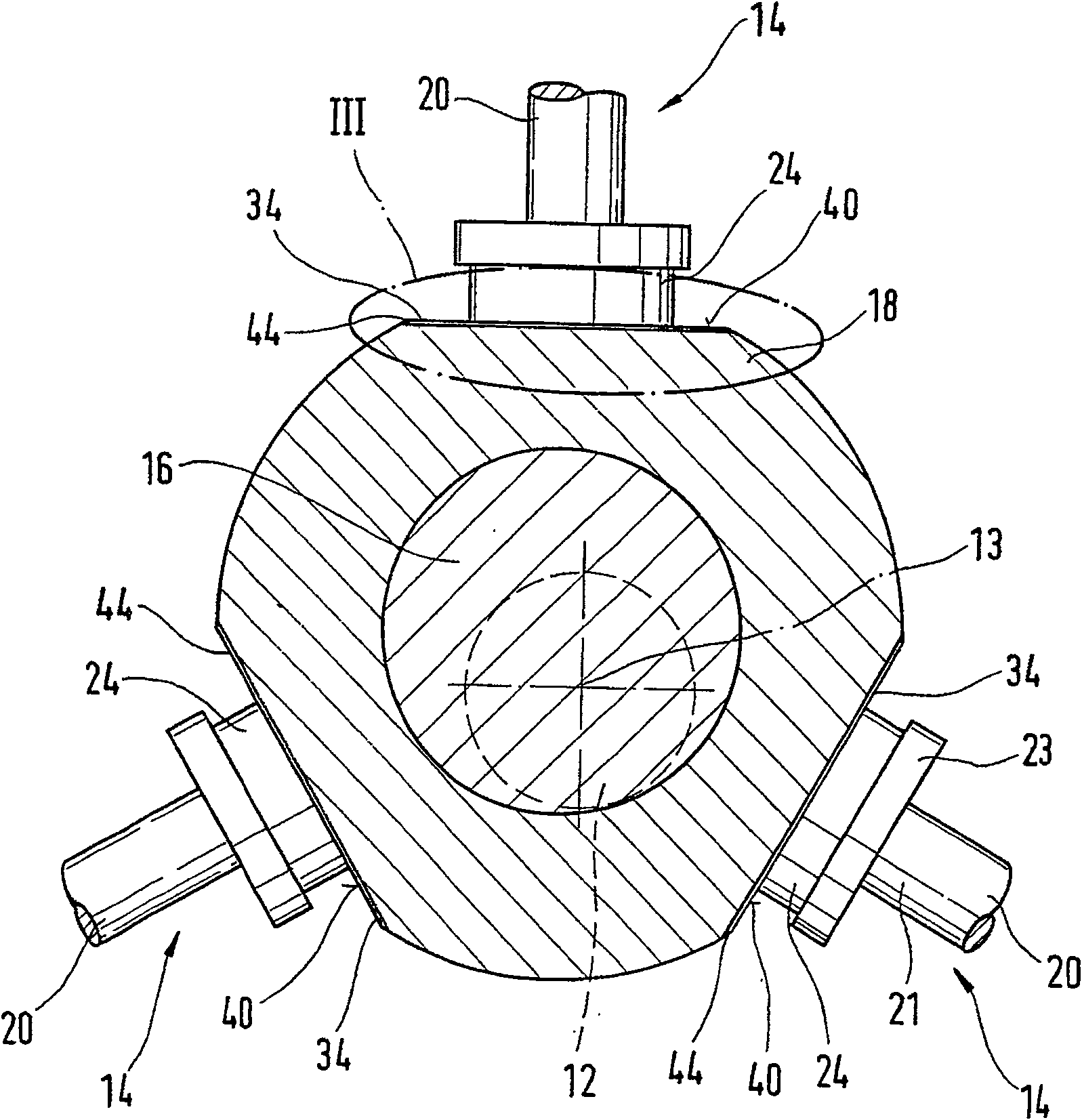
[0012] exist Figures 1 to 6 shows a high-pressure pump for a fuel injection system of an internal combustion engine of a motor vehicle, for example, which is designed as a radial piston pump. Via the high-pressure pump, fuel is delivered at a high pressure of up to 2000 bar into, for example, a storage tank, from which the fuel is withdrawn for injection into the internal combustion engine. The high-pressure pump has a housing 10 in which a drive shaft 12 is mounted rotatably about an axis 13 . At least one, preferably a plurality of pump elements 14 , which are driven by the drive shaft 12 , are accommodated in the housing 10 . The drive shaft 12 has a shaft section 16 configured eccentrically to its axis of rotation 13 , on which a ring 18 is rotatably mounted. The pump elements 14 each have a pump plunger 20 , which is guided displaceably and sealingly in a cylinder bore 22 extending at least approximately radially to the axis of rotation 13 of the drive shaft 12 . The ...


PUM


Abstract

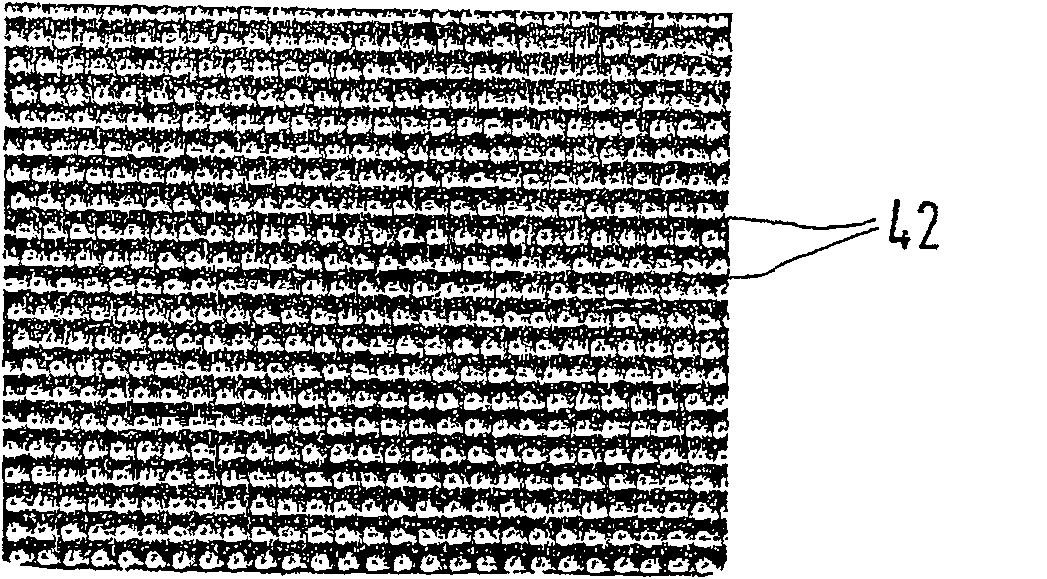
The high-pressure pump has a drive shaft (12) and at least one pump element (14), which has a pump plunger (20) driven in reciprocating linear motion via the drive shaft (12), wherein during the drive On a shaft section (16) of the shaft (12) arranged eccentrically with respect to its axis of rotation (13), a ring (18) is rotatably supported, and the pump plunger (20) passes through a support element (24) Supported on this ring (18). The ring (18) and / or the supporting element (24) has a large number of dimples (42) at least in its contact area, and on the ring (18) and / or the supporting element (24), at least in its A solid lubricant layer (40) is applied in the contact area.

Description

technical field [0001] The invention relates to a high-pressure pump for a fuel injection system of an internal combustion engine, which has a drive shaft and at least one pump element with a pump plunger driven in reciprocating linear motion via the drive shaft, wherein On a shaft section of the drive shaft that is arranged eccentrically with respect to its axis of rotation, a ring is rotatably mounted on which the pump plunger is supported via a bearing element. Background technique [0002] One such high-pressure pump is known from DE 198 29 548 A1. The high-pressure pump has a drive shaft and at least one pump element with a pump plunger driven in reciprocating linear motion via the drive shaft. The drive shaft has a shaft section configured eccentrically with respect to its axis of rotation, on which a ring is rotatably mounted. The pump plunger is supported on the ring via a bearing element. The rotary motion of the drive shaft is converted into the reciprocating li...

Claims


Application Information

Patent Timeline
Patent Type & Authority Patents(China)
IPC IPC(8): F04B1/053F02M59/10F02M63/00F02M63/02F04B1/04
CPCF04B1/0413F02M59/102F02M63/0001F02M63/0225F04B1/0426F04B1/053F05C2203/0808F05C2203/086F05C2203/0882F05C2225/04F05C2251/14F05C2253/12
Inventor 托马斯·克莱恩贝克安德烈亚斯·沃格特亚历山大·雷德利希马库斯·科赫
Owner ROBERT BOSCH GMBH
Learn More