
Pump

A technology for pumping and pump housings, applied in the field of pumps, can solve problems such as time-consuming adjustments, and achieve the effects of improving convenience, enhancing performance, and preventing backflow or leakage

Inactive Publication Date: 2009-12-02
PANASONIC ELECTRIC WORKS CO LTD
View PDF7 Cites 0 Cited by
  • Summary
  • Abstract
  • Description
  • Claims
  • Application Information

AI Technical Summary

Problems solved by technology

[0009] However, in the self-priming pump disclosed in Reference 1, it takes time to adjust the gap because the gap is controlled by fine adjustment of the partition plate at a precise position and fixed there by mechanical screws

Method used


Image

  • Pump
  • Pump
  • Pump

Examples


Embodiment Construction

[0027] An embodiment of the present invention, which constitutes a part of the present invention, will be described in detail below with reference to the accompanying drawings.

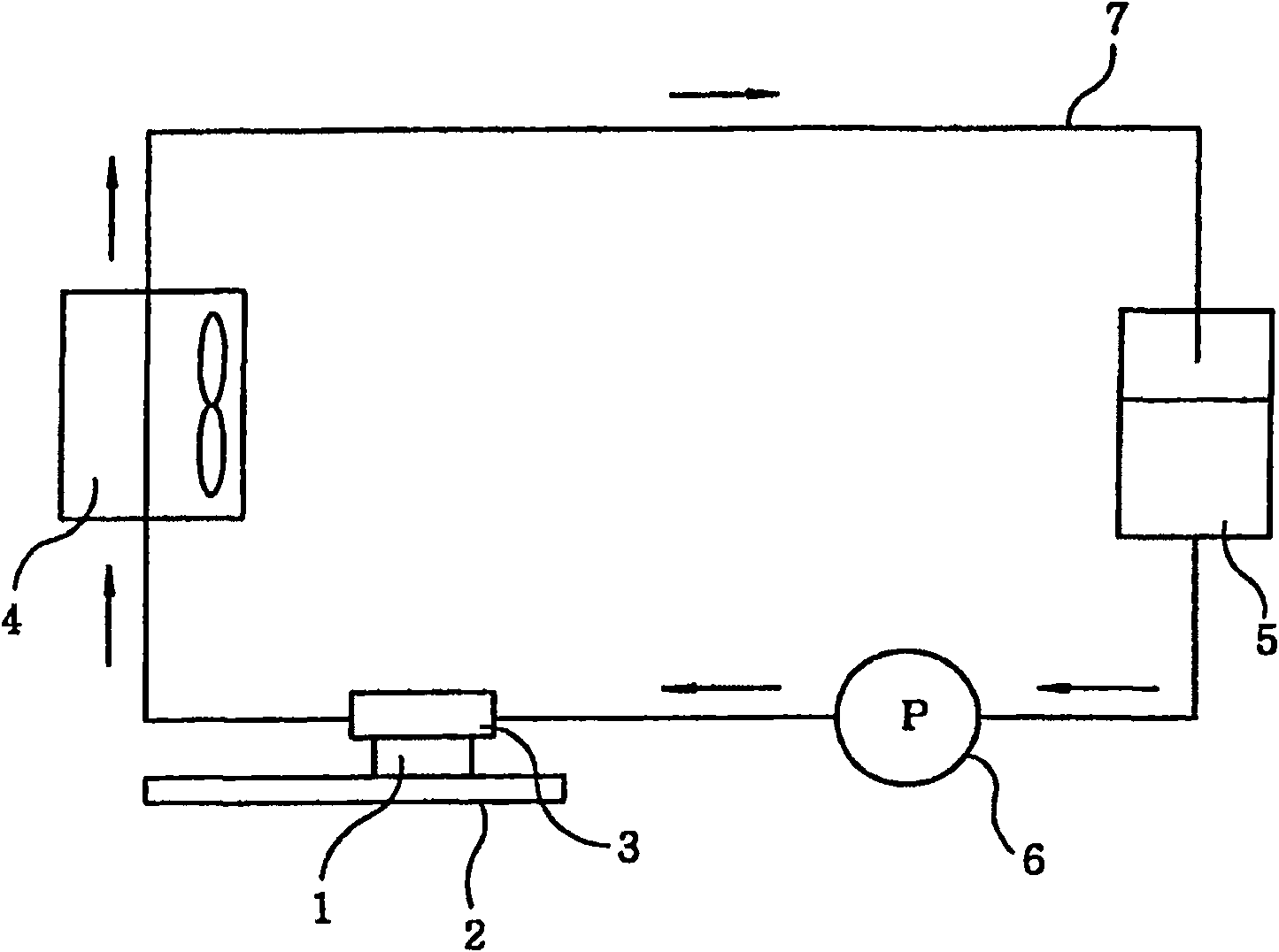
[0028] like figure 1 As shown, the coolant circulation system includes a heating element 1 mounted on a substrate 2, and a heat sink unit 3 such as a radiator for cooling the heating element 1 by exchanging heat with the heating element 1 using a coolant (such as water) Allow to cool.

[0029] The coolant circulation system also includes a radiator 4 for removing heat from the coolant; a storage tank 5 for storing the coolant therein; a pump for circulating the coolant; and a pipeline 7 for disabling heat The sink unit 3, radiator 4, storage tank 5 and pump 6 are connected.

[0030] The coolant in the storage tank 5 is discharged from the pump 6 through the line 7 to flow into the heat sink unit 3 . In the heat sink unit 3, heat is transferred from the heat generating element 1 to the coolant, so t...


PUM


Abstract

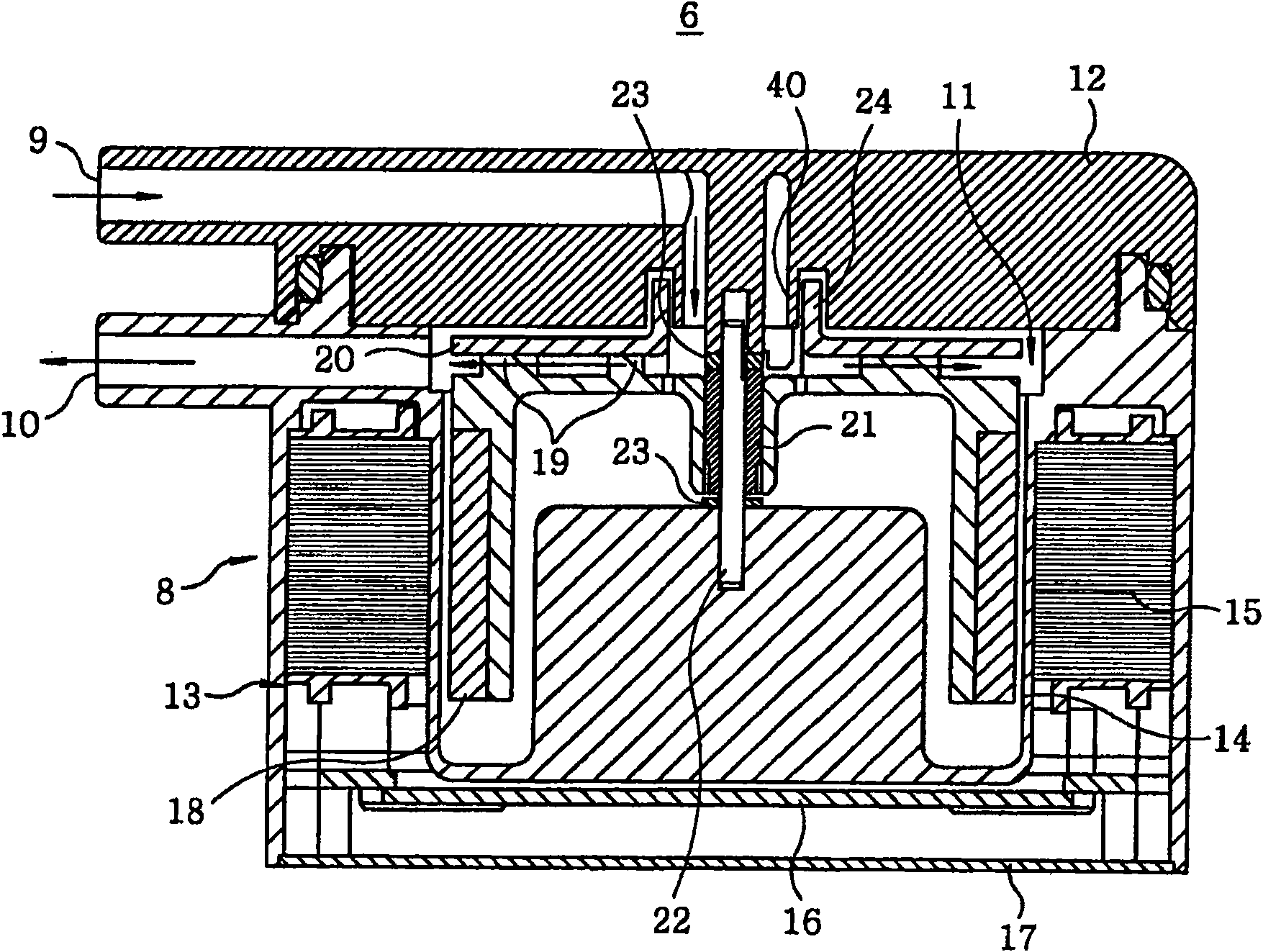
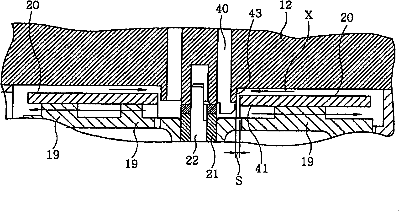
A pump includes a pumping unit including therein an impeller for sucking and discharging a liquid; and a pump case accommodating therein the pumping unit and provided with an inlet for sucking the liquid into the pump and an outlet for discharging the liquid out of the pump. The impeller has an inlet mouth portion of a cylindrical shape that projects towards the pump case, and the pump case has a case inlet portion and an annular recess portion which the inlet mouth portion of the impeller is movably inserted in and is formed at the vicinity of the case inlet portion.

Description

technical field [0001] The present invention relates to a pump driven by a motor to suck and discharge liquid. Background technique [0002] In a pump that is mainly used for water circulation and is always filled with water, there is a possibility that water may leak through the shaft seal portion. In view of this, for example, a hermetic motor pump has been widely used, which does not use a shaft seal structure but a structure in which a water flow portion having an impeller is separated from a driving mechanism portion having a motor. [0003] Such a canned motor pump is configured such that a rotor integrally formed with an impeller is accommodated in a partition wall to be sealed, so that the shaft is not sealed. The rotor is rotated by the rotating magnetic force generated by the stator located outside the partition wall, and the magnetic force acts on the rotor through the partition wall. [0004] In addition, a magnetic coupling type electromagnetic drive pump is a...

Claims


Application Information

Patent Timeline
Patent Type & Authority Patents(China)
IPC IPC(8): F04D29/44
CPCF04D29/167F04D29/4273F04D29/0413F04D13/0633F04D29/047
Inventor 阿南哲也酒井敏辅福木晴海
Owner PANASONIC ELECTRIC WORKS CO LTD
Learn More