Floating type oval-shaped supersonic vibration micro-engraving device

An ultrasonic vibration and floating technology, which is applied in the directions of driving devices, fluids using vibration, large fixed members, etc., can solve the problems of restricting the application research of microgrooves with special functions, not suitable for single-piece small batch production, and low precision of groove width.

Inactive Publication Date: 2009-12-09
BEIHANG UNIV
View PDF2 Cites 1 Cited by
  • Summary
  • Abstract
  • Description
  • Claims
  • Application Information

AI Technical Summary

Problems solved by technology

Micro-milling is easy to control the cross-sectional shape of micro-grooves, but the burrs are large during milling, the accuracy of groove width is low, and the cutting depth is easily affected by the positioning error of the machine tool; micro-forging processing has high forming efficiency and no burrs, but it needs to be manufactured first Out of the mold, it is not suitable for single-piece and small-batch production; the groove width of laser engraving has high precision, but the cross-sectional shape of the micro-groove is difficult to control
In summary, the original method of processing microgrooves on complex curved surfaces often has low precision and poor quality, and the cross-sectional shape is difficult to meet the design requirements. These problems directly limit the application research of special functional microgrooves on complex curved surfaces.

Method used


Image

  • Floating type oval-shaped supersonic vibration micro-engraving device
  • Floating type oval-shaped supersonic vibration micro-engraving device
  • Floating type oval-shaped supersonic vibration micro-engraving device

Examples


Embodiment Construction

[0025] The present invention will be further described in detail below in conjunction with the accompanying drawings.

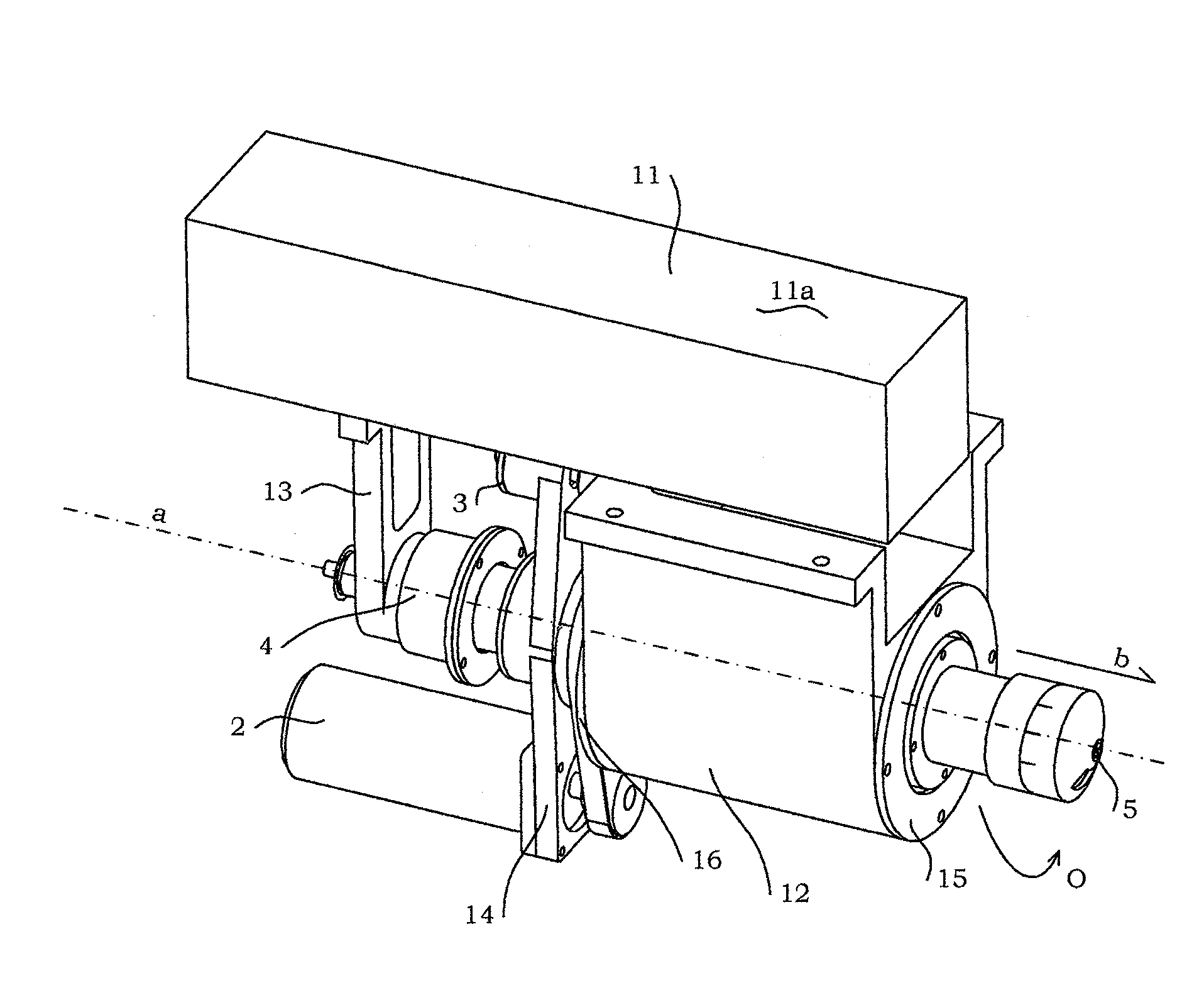
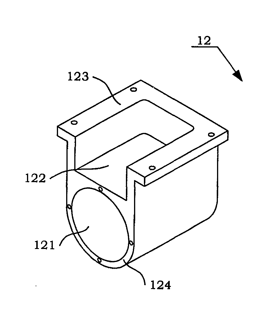
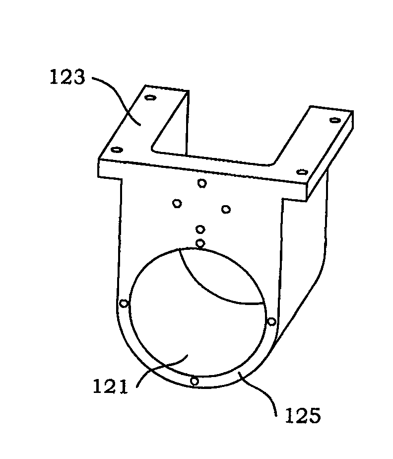
[0026] The floating elliptical ultrasonic vibration micro-engraving device of the present invention can generate elliptical ultrasonic vibration to realize micro-engraving under the drive of an ultrasonic transducer. The micro-engraving device of the present invention uses the floating transducer assembly to ensure that the depth of the processed groove remains constant; and then uses the longitudinal bending transducer to make the tool generate ultrasonic elliptical vibration, and cutting with the help of ultrasonic elliptical vibration can reduce cutting force, improve processing accuracy and reduce The characteristics of surface roughness to ensure that the grooves on the surface of the machined parts have high geometric accuracy and surface quality and the edges are free of burrs; The defect of rotation realizes freely adjustable engraving in multiple cut...


PUM


Abstract

The invention discloses a floating elliptical ultrasonic vibration micro-engraving device, which comprises a mounting table (11), a support unit, a drive unit (2), a sliding unit (3), a floating transducing component (4), a longitudinal bending transducing device (1); support base (12), A support (13), B support (14) constitute a support unit; the lower mounting surface of the mounting table (11) is connected with support base (12), A support (13) respectively, The upper mounting surface (11a) of the mounting table (11) is connected with the numerical control workbench. Driven by the ultrasonic transducer, the cutting tool of the engraving device of the present invention can generate elliptical ultrasonic vibrations to realize micro-engraving. The micro-engraving device of the present invention uses the floating transducer assembly to ensure that the depth of the processed groove remains constant; and then uses the longitudinal bending transducer to make the tool generate ultrasonic elliptical vibration, and cutting with the help of ultrasonic elliptical vibration can reduce cutting force, improve processing accuracy and reduce The characteristics of surface roughness to ensure that the groove on the surface of the machined part has high geometric accuracy and surface quality and the edge is free of burrs; the combined design of the longitudinal bending transducer and the drive unit makes up for the inability of the tool in traditional planing The defect of rotation realizes freely adjustable engraving in multiple cutting directions.

Description

technical field [0001] The invention relates to a micro-engraving device, more particularly, a floating elliptical ultrasonic vibration micro-engraving device capable of processing microgrooves on complex curved surfaces. Background technique [0002] Processing tiny grooves with special structures on the surface can enable the surface to obtain some specific functions, such as drag reduction, stealth, frequency selection, etc. These functions can play an important role in aviation, aerospace and other industrial fields, and the surface of aerospace products is mostly Complex curved surface, which requires those special functional micro-grooves to be processed on complex curved surface. At present, the domestic and foreign methods of processing micro-grooves on complex curved surfaces mainly include micro-milling, micro-forging, laser engraving, etc. Micro-milling is easy to control the cross-sectional shape of micro-grooves, but the burrs are large during milling, the groo...

Claims


Application Information

Patent Timeline
Patent Type & Authority Patents(China)
IPC IPC(8): B23B41/00B23C3/28B23Q1/01B23Q5/04B06B1/06
Inventor 张德远李翔韩鑫肖华
Owner BEIHANG UNIV
Why Eureka
Try Eureka