Truncated platform composite material member and metal member positioning adhesion process

A composite material and frustum-shaped technology, which is applied in the direction of adhesives, connecting components, and bonding methods, can solve problems such as uneven thickness of the adhesive layer, waste, and misalignment of products, and achieve high axial positioning accuracy and ensure circumferential alignment. The effect of positioning and axial force uniformity

Active Publication Date: 2010-01-27
AEROSPACE RES INST OF MATERIAL & PROCESSING TECH
View PDF5 Cites 0 Cited by
  • Summary
  • Abstract
  • Description
  • Claims
  • Application Information

AI Technical Summary

Problems solved by technology

If the traditional manual pressing method is used, the distance from the upper edge of the square protrusion to the bottom of the metal part cannot be measured during the travel of the frustum-shaped composite material part, and the axial displacement of the frusto-conical composite material part cannot be effectively controlled; Stability, the frustum-shaped composite material part shakes during the assembly process, and it is impossible to position the frustum-shaped composite material part circumferentially, resulting in different axes of the bonded products, uneven thickness of the adhesive layer, and the upper edge of the square protrusion of the frustum-shaped composite material part. The distance from the bottom of the metal part exceeds the specified range
The pass rate of traditional manual pressure bonding is only 60%. Since the adhesive used for bonding is thermosetting resin, it causes great waste

Method used


Image

  • Truncated platform composite material member and metal member positioning adhesion process
  • Truncated platform composite material member and metal member positioning adhesion process
  • Truncated platform composite material member and metal member positioning adhesion process

Examples


Embodiment 1

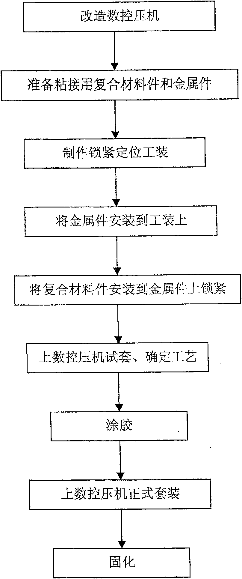
[0050] The flow chart of positioning bonding is as follows: figure 1 shown.

[0051] 1. Transformation of CNC press

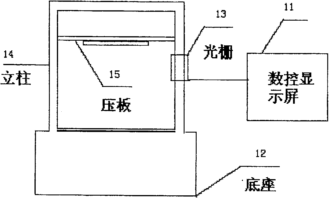
[0052] Such as figure 2 The numerically controlled press shown includes a numerically controlled display screen 11, a base 12, a grating 13, a column 14, and a pressing plate 15. The numerically controlled display screen 11 is connected to the grating 13 through a data line, and the grating 13 is installed on the column 14. Above, the mechanical connection between the column 14 and the pressing plate 15 .

[0053] The numerical control display screen 11 can automatically display the set force and the displacement of the composite material parts, which could not be realized in the previous bonding process. The pressing plate 15 of the numerical control press is driven by a lead screw, and pressurized to apply force to the truncated circular composite material piece. The mechanical force is uniform, effective, and highly controllable, and is not affected by...

Embodiment 2

[0067] The parameters of the CNC press during the test set, σ is taken as 10Kn, and γ is taken as 0.4mm / min;

[0068] When the distance from the upper edge of the square protrusion of the frustum-shaped composite material piece to the bottom end of the frustum-shaped metal piece is 688.8 mm, the position of the frustum-shaped composite material piece is recorded by the grating 13 of the numerical control press. The gap between the frustum-shaped composite material part and the frustum-shaped metal part is 1.5mm, which exceeds the specified 0.8mm. After wrapping 4 layers of glass cloth tape on the outer surface of the frustum-shaped metal part, squeeze out the excess gap space.

[0069] The glue thickness is 0.35mm.

[0070] According to the formula σ=η·γ, determine the parameters of the CNC press in the formal suit. γ is 0.18mm / min, and σ is 20Kn. Input the determined σ and γ into the CNC press, and start the formal suit. When the CNC press presses the platen The CNC press st...

Embodiment 3

[0074] For the parameters of the CNC press during the test set, σ is taken as 15Kn, and γ is taken as 0.5mm / min;

[0075] When the distance from the upper edge of the square protrusion of the frustum-shaped composite material piece to the bottom end of the frustum-shaped metal piece is 688.2 mm, the position of the frustum-shaped composite material piece is recorded by the grating 13 of the numerical control press. The gap between the frustum-shaped composite material part and the frustum-shaped metal part is 1.6mm, which exceeds the specified 0.8mm. After wrapping 4 layers of glass cloth tape on the outer surface of the frustum-shaped metal part, the excess gap space is squeezed out.

[0076] The glue thickness is 0.4mm.

[0077] According to the formula σ=η·γ, determine the parameters of the CNC press during the formal assembly. γ is 0.2mm / min, and σ is 22Kn. Input the determined σ and γ into the CNC press to start the formal assembly. When the CNC press presses the platen ...


PUM

PropertyMeasurementUnit
thicknessaaaaaaaaaa

Abstract

The invention relates to a positioning and bonding technology of a truncated-cone-shaped composite material part and a truncated cone-shaped metallic part. The technology comprises: the modification of a numerical control presser used for positioning and bonding, the manufacture of tooling for locking and positioning, trial assembly, glue application, official assembly, curing and the like. The technology adopts the specially designed tooling for locking and positioning and solves the technical problem of precise positioning in bonding process; the numerical presser is adopted to press assembly parts and as the axial force imposed by the numeric presser is even and stable, axial displacement generated during the traveling process of heat insulating sleeves of the assembly parts is prevented so as to guarantee the axial positioning and the consistency in axial degree of products after bonding; the technology adopts the numerical presser to press the assembly parts and has high precision in axial positioning, and the effective displacement quantity of the truncated-cone-shaped composite material part can be precisely controlled so as to guarantee that the square erection of the truncated cone-shaped composite material part can cross the distance up to the bottom of the truncated cone-shaped metallic part. The technology is used and promoted in practice, with a one-time bonding qualified rate up to over 99 percent, thereby greatly saving raw materials.

Description

technical field [0001] The invention relates to a positioning bonding process for a frustum-shaped composite material part and a frustum-shaped metal part, and belongs to the bonding field of composite materials and metal materials. Background technique [0002] Composite materials have light weight, high temperature resistance, high heat resistance, ablation resistance, etc., and their load-bearing performance is not as good as that of metal materials. They are usually formed in one piece, and generally do not process threaded holes and other connection holes; while metal materials have good load-bearing performance and can be processed. Threaded holes, pin holes, etc. can also be connected to the bracket, but most metal materials are denser and heavier than composite materials, and have poor ablation resistance, which cannot reach the high temperature resistance of composite materials of several thousand degrees. Therefore, in order to combine the excellent properties of m...

Claims


Application Information

Patent Timeline
Patent Type & Authority Patents(China)
IPC IPC(8): F16B11/00C09J5/00
Inventor 马蕾王泽华
Owner AEROSPACE RES INST OF MATERIAL & PROCESSING TECH
Why Eureka
Try Eureka