Repeatable usable drawing rivet, and method of using same

A technology for pulling rivets and rivets, applied in the direction of rivets, etc., can solve the problems of easy loosening, poor firmness, and difficult disassembly of the structure.

Active Publication Date: 2010-02-03
MEISHAN CRRC FASTENING SYST CO LTD
View PDF8 Cites 0 Cited by
  • Summary
  • Abstract
  • Description
  • Claims
  • Application Information

AI Technical Summary

Problems solved by technology

[0004] But the above-mentioned 'ring groove rivets' have the following disadvantages: i. cannot be reused, that is, it is difficult to disassemble structurally, and is only suitable for parts that do not need to be disassembled
iv. After riveting, all the pulling rods at the rear end of the separation tank are lost, resulting in a large waste of material
[0005] The (ZL01138321.6) disclosed by the Chinese patent is a detachable blind rivet, but the two mutually riveted bodies are riveted with threads, and the thread riveted is connected with the ring of the above-mentioned 'ring groove rivet'. Groove riveting ratio, poor firmness, easy to loosen, the friction between the two objects being connected is weakened, all the force is on the nail rod during operation, and it is easy to fatigue and fracture when subjected to vibration

Method used


Image

  • Repeatable usable drawing rivet, and method of using same

Examples


Embodiment 1

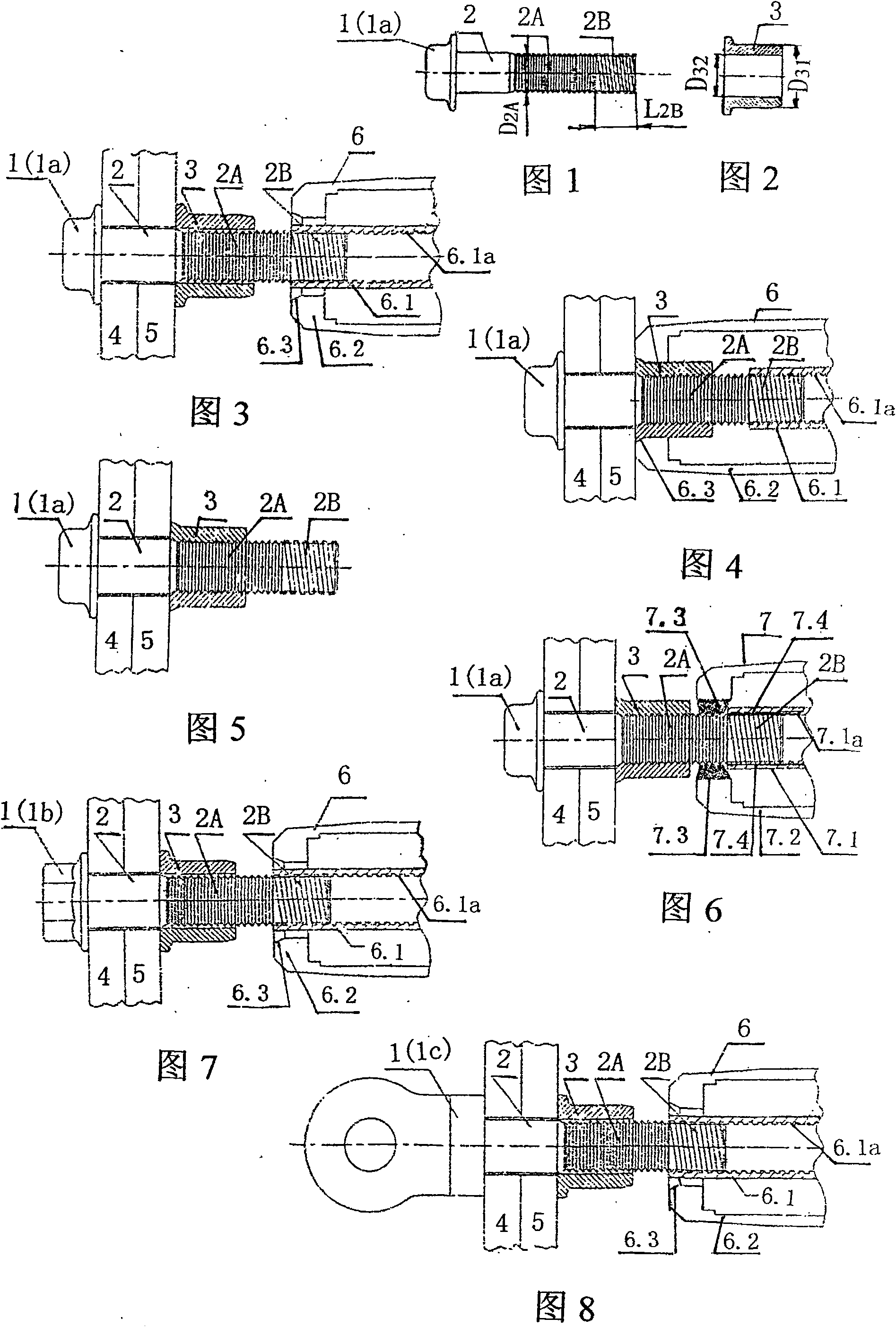
[0031] See figure 1 , figure 2 , The present embodiment 1 is a reusable blind rivet, which consists of a nail head 1, a nail shank 2 and a collar 3. The nail head 1 is a pan head 1a. The nail shank 2 is composed of a ring groove segment 2A at the front end and a ring groove segment 2A that is press-fitted with the collar 3 and an external thread segment 2B at the rear end. There is a short transition section between the two sections for processing.

[0032] In Example 1, a pull rivet can be used repeatedly to mark the diameter D=20mm, and the value of the outer diameter of the ring groove section is D 2A =19.2-20.2, length L of external thread segment 2B 2B =18.3-20.3. The outer diameter of the collar is D 31 =30.3-31.3, inner diameter value D 32 =19.3-20.3.

[0033] Riveting steps:

[0034] i. see image 3 , the nail rod 2 passes through the two objects 4 and 5 to be connected, the pan head 1a is close to the surface of the object 4, the collar 3 is set on the ring...

Embodiment 2

[0037] Example 2: see Figure 7 , The nail head 1 adopts a hexagonal flange 1b, which is used in the case where the rivet needs to be prevented from rotating during the riveting process. All the other structures and methods of use are exactly the same as in Example 1.

[0038]See figure 1 , figure 2 , this embodiment 2 can repeatedly use a pull rivet to mark the diameter D = 16mm, and the value of the outer diameter of the ring groove section is D 2A =15.1-16.1, length L of external thread section 2B 2B =17.2-19.2, the outer diameter of the collar is D 31 =25, 1-26.1, inner diameter value D 32 = 5.8-16.8.

Embodiment 3

[0039] Embodiment 3: see Figure 8 , Nail head 1 adopts eye ring 1c, which is used when other components need to be installed on the rivet. All the other structures and methods of use are exactly the same as in Example 1.

[0040] See figure 1 , figure 2 , this embodiment 3 can repeatedly use a pull rivet to mark the diameter D = 16mm, and the outer diameter of the ring groove section is D 2A =15.1-16.1, length L of external thread section 2B 2B =17.2-19.2, the outer diameter of the collar is D 31 =25.1-26.1, inner diameter value D 32 = 5.8-16.8.


PUM


Abstract

This invention relates to a pull-rivet used repeatedly and its usage, in which the rivet is composed of a nailhead, a nailrod and a ringer, and the nailrod is composed of a ring slot section at the front extrusion-matched with the ringer and an outer screw part at the end, which eliminates original separation groove and end nail-rod compared with present ring-slot rivets and saves material by 40%,the outer screw thread part of the rear end of a nail rod is used in either connecting with the screw thread rotating inner jacket of the riveter or removing the connection and forms a cutter with ablade in the jacket of the riveter, which moves forward along the jacket axially to cut ringers down and nail rod can be used again.

Description

(1) Technical field: [0001] The invention discloses a reusable blind rivet and its use method, belonging to the category of fasteners (F16B). (two) background technology: [0002] For a long time, steel structures such as railway wagons, automobiles, and bridges have used hot riveted ordinary rivets, whose chemical composition and mechanical properties are equivalent to 4.8-grade bolts, resulting in low connection reliability of the steel structure, short maintenance cycle, and post-maintenance costs. High-level problems, unable to meet the requirements of "heavy load and speed increase" of freight. And hot rivet installation labor intensity is big, and voice is big, pollutes environment. Therefore, it is very urgent and necessary to adopt new fasteners in the key and key parts of the above-mentioned steel structure. [0003] Chinese patent discloses a new type of fastener 'blind rivet' (ZL200520035325X, reference document 1) which solves the above problems and produces th...

Claims


Application Information

Patent Timeline
Patent Type & Authority Patents(China)
IPC IPC(8): F16B19/04
Inventor 肖颖伏凯胡方年
Owner MEISHAN CRRC FASTENING SYST CO LTD
Why Eureka
Try Eureka