
Projection rotating center measurement method suitable for 2D-CT scanning system

A technology of rotation center and scanning system, which is used in measurement devices, computer tomography scanners, photography, etc., to achieve the effect of improving detail resolution and improving measurement accuracy

Inactive Publication Date: 2010-02-03
BEIHANG UNIV
View PDF3 Cites 0 Cited by
  • Summary
  • Abstract
  • Description
  • Claims
  • Application Information

AI Technical Summary

Problems solved by technology

It has the characteristics of simple operation and high measurement accuracy

Method used


Image

  • Projection rotating center measurement method suitable for 2D-CT scanning system
  • Projection rotating center measurement method suitable for 2D-CT scanning system
  • Projection rotating center measurement method suitable for 2D-CT scanning system

Examples


Embodiment Construction

[0040] The present invention will be further described in detail below in conjunction with the accompanying drawings.

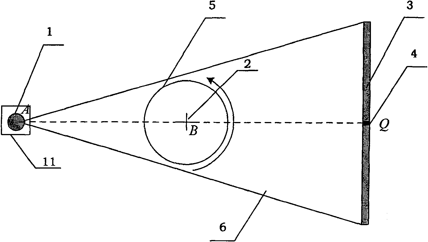
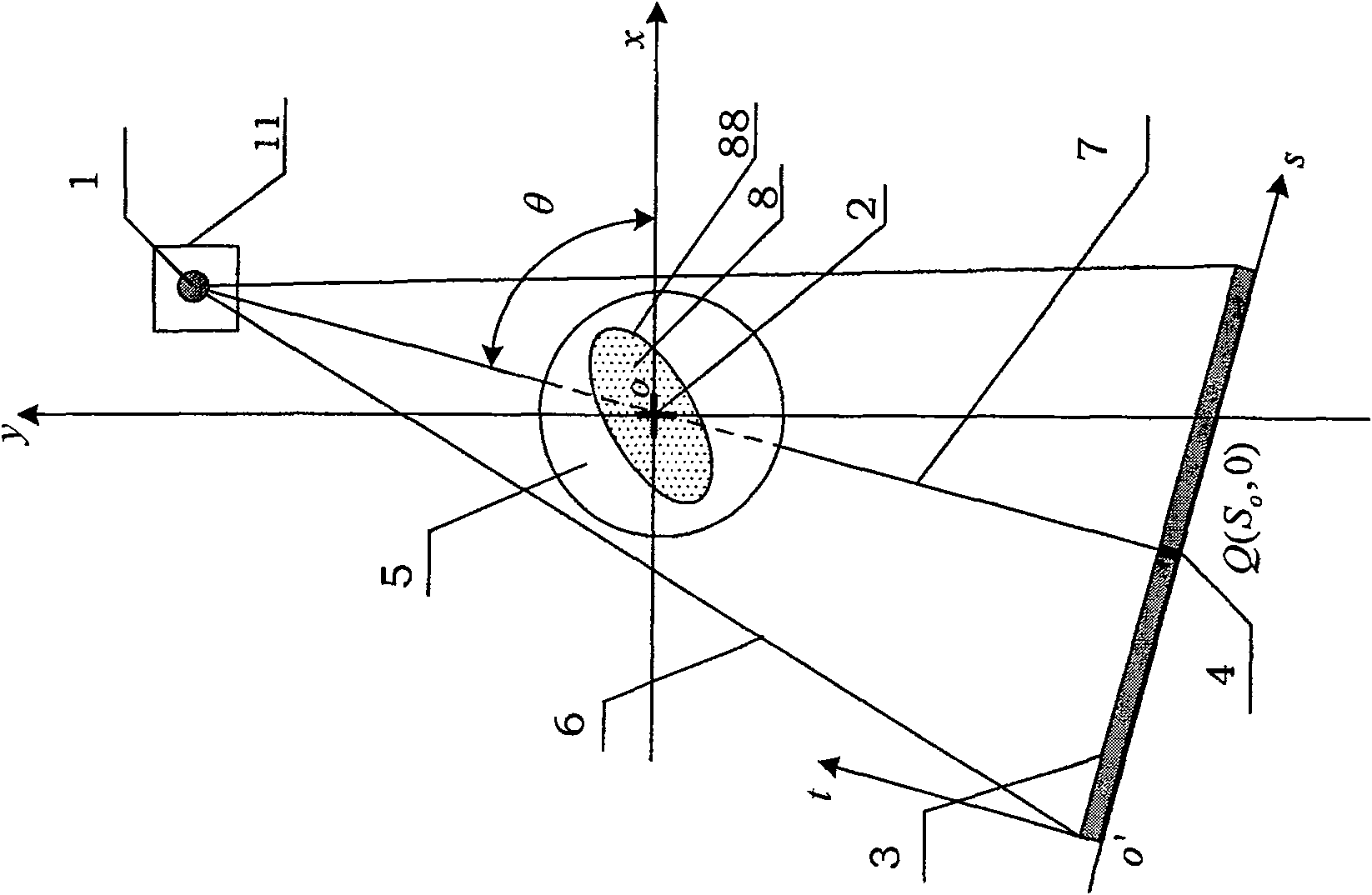
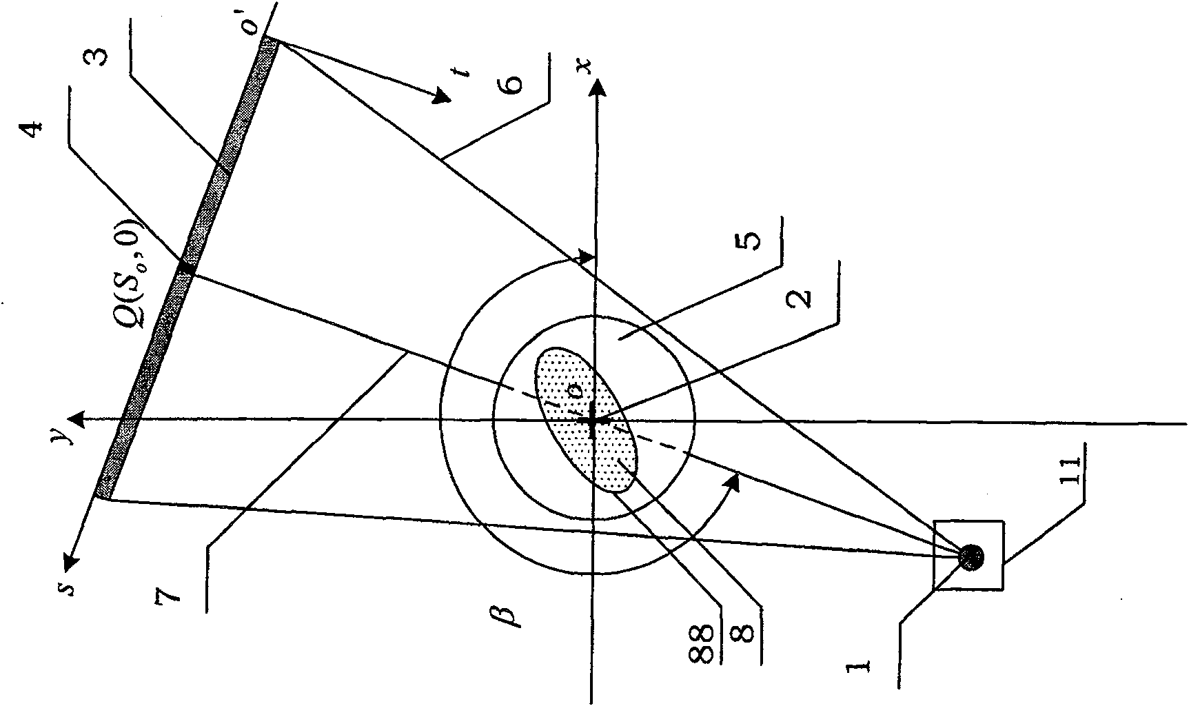
[0041] The present invention is a projection rotation center measurement method suitable for 2D-CT scanning system, which uses the principle of projection symmetry of fan beam ray scanning two-dimensional CT to measure the position Q(S o , 0). The connection line between the ray source focal point 1 of the ray source 11 and the scanning table rotation center point 2 of the scanning table 5 is called the AB connection line. The extension line of the AB connection line intersects the linear array detector 3 at a point Q (ie, the intersection point Q), The intersection point Q is the projection point of the scanning table rotation center point 2 on the linear array detector 3, which is called the projection rotation center point 4. It can also be referred to as the central ray 7 emitted by the ray source 11 passing the scanning table rotation center point 2 of the ...


PUM


Abstract

The invention discloses a method applicable to measurement of the projection and rotation center of a 2D-CT scanning system, which is dedicated to measurement of the projection and rotation center ofa 2D-CT (Two Dimensional Computed Tomography) scanning system based on linear array detectors, and is applicable to measurements related to DR (Digital Radiography) and 2D-CT / 3D-CT imaging in medicaland industrial domains. The method, employing the principle of projection symmetry of 2D-CT with fanning beam scanning for measuring the position Q(S[o], 0) of the projection and rotation center point, is simply operable and highly accurate in measurement.

Description

Technical field [0001] The invention relates to a measurement suitable for the projection rotation center of a two-dimensional CT scanning system, which is aimed at the measurement of the projection rotation center of a 2D-CT (Two Dimensional Computed Tomography) scanning imaging system based on a linear array detector, and can be used in the medical and industrial fields Related measurement in the imaging process of DR-DigitalRadiography, two-dimensional and three-dimensional computer tomography (2D-CT / 3D-CT). Background technique [0002] Fan beam ray scanning two-dimensional CT based on linear array detector, its scanning principle is as follows figure 1 Shown. In the figure, the connection line between the ray source focal point 1 of the ray source 11 and the scanning table rotation center point 2 of the scanning table 5 is called the AB connection. The extension line of the AB connection and the linear array detector 3 intersect at a point Q (ie, the intersection point). Q)...

Claims


Application Information

Patent Timeline
Patent Type & Authority Patents(China)
IPC IPC(8): G01B11/00A61B6/03G01N23/04G03B42/02
Inventor 李保磊杨民刘静华吴文晋王钢
Owner BEIHANG UNIV
Learn More