Highly effective electromagnetical spiral drying apparatus

A drying equipment and spiral technology, which is applied in the field of high-efficiency electromagnetic spiral drying equipment, can solve the problems of equipment aging energy consumption, long heating auxiliary time, and difficulty in controlling the moisture content of materials, so as to achieve less heat conduction loss and reduce maintenance investment in the later stage Effect

Inactive Publication Date: 2010-03-24
西安市南郊航天安装机械厂
View PDF5 Cites 2 Cited by
  • Summary
  • Abstract
  • Description
  • Claims
  • Application Information

AI Technical Summary

Problems solved by technology

The existing drying method, the equipment is aging and the energy consumption is high, manual operation is the main method, and the working environment is labor-intensive, especially the drying method of the flat iron plate, because the drying time of the material needs to be shortened at the work site, and the material needs to be kept Mixing, the working environment is full of dust, which not only wastes increasingly scarce resources, but also seriously affects the health of operating staff
The quality of the dried product is unstable, and the moisture content of the material is difficult to control
Whether it is the way of flat iron plate straight kang or the heating source of spiral conveying steam drying, it is coal-fired to transfer heat directly or indirectly, and the utilization rate of heat energy is low. The equipment has long drying time for materials, large energy consumption, and low heat conduction efficiency. The phenomenon of high consumption and low output such as long heating auxiliary time
The soot emitted by the combustion brings serious pollution to the surrounding environment

Method used


Image

  • Highly effective electromagnetical spiral drying apparatus
  • Highly effective electromagnetical spiral drying apparatus

Examples


Embodiment Construction

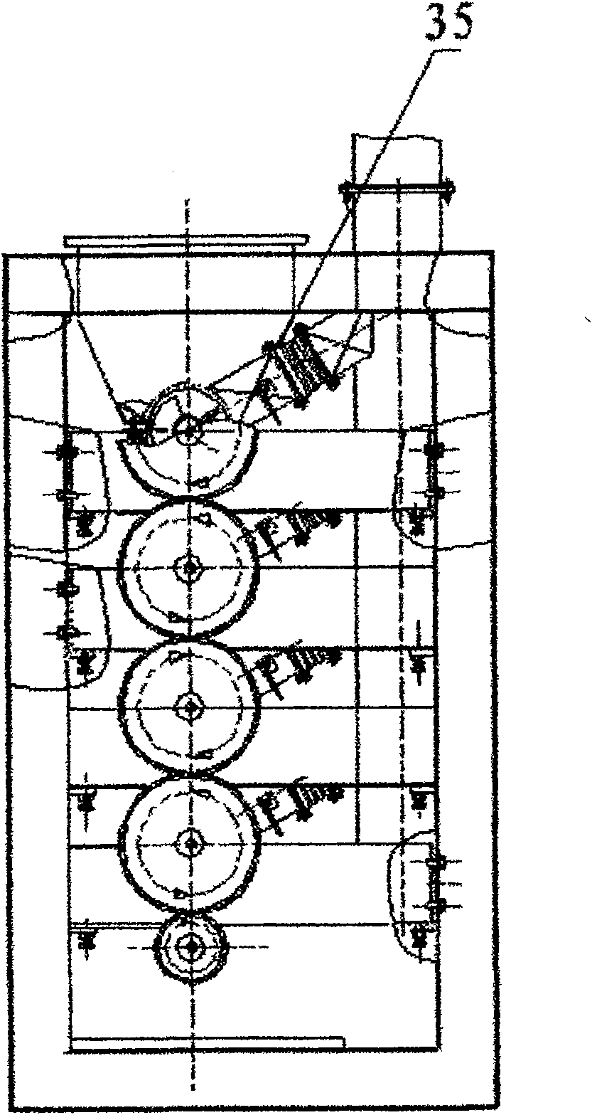
[0022] The specific implementation is as figure 1 and figure 2 As shown; the transmission stirring device fixed on the frame 8 includes a hollow tube distributed from top to bottom, inside the hollow tube there is a screw blade shaft 22 fixed along its tube axis, and the left and right ends of the screw blade shaft 22 are respectively connected with an input bearing seat 13 , Rear bearing seat 24; The input bearing gland 12 of the left end and the right end is sleeved on the two ends of the input bearing seat 13 and the rear bearing seat 24 and fixed by the lock nut 11. The left end of the helical blade shaft 22 is respectively axially connected with the first to fourth transmission gears 10, 14, 16, 17, and the teeth of the first to fourth transmission gears 10, 14, 16, 17 are meshed with each other. One end of each hollow tube has a feed port, and the other end has a discharge port, and the top hollow tube feed port communicates with the feed box 23 . The hollow tube ...


PUM


Abstract

The invention relates to a high efficient electromagnetic spiral drying device, which is characterized in that: a driving and stirring device comprises a hollow tube distributed from top to bottom; the hollow tube is provided with a spiral blade shaft which is fixed along a tube shaft of the hollow tube; the right end of the spiral blade shaft is respectively connected with bearings of a rear bearing seat (24); the left end of the spiral blade shaft is respectively connected with driving gears; the driving gears are engaged with one another; a discharge port of the hollow tube is communicatedwith a feed port of the hollow tube; an outer layer of the hollow tube is provided with an electromagnetic heating unit formed by wound spiral hollow tubes; a control device controls the driving gearsto rotate in a reverse direction, so as to drive spiral blades to rotate; adhesive wet materials are put into the hollow tube from the feed port of the hollow tube by a feed transmission device; theadhesive wet materials are continuously turned over, stirred, revolved and delivered, is continuously heated at various heating sections for evaporating moisture of the materials; and the heated and dried materials are continuously discharged out of the spiral tubes. The high efficient electromagnetic spiral drying device has the advantages of high heat energy utilization rate, short material drying time, low energy consumption and environment pollution reduction.

Description

technical field [0001] The invention relates to drying and drying equipment for various metal concentrate powders in a washing plant of the non-ferrous metal mining industry, in particular to a high-efficiency electromagnetic spiral drying equipment. Background technique [0002] At present, the drying of various non-ferrous metal concentrates in China generally adopts the original flat iron plate straight kang method, and only a few large enterprises use spiral conveying steam for drying. The existing drying method, the equipment is aging and the energy consumption is high, manual operation is the main method, and the working environment is labor-intensive, especially the drying method of the flat iron plate, because the drying time of the material needs to be shortened at the work site, and the material needs to be kept Mixing will cause dust to fly in the working environment, which not only wastes increasingly scarce resources, but also seriously affects the health of ope...

Claims


Application Information

Patent Timeline
Patent Type & Authority Patents(China)
IPC IPC(8): F26B17/20F26B3/24F26B25/02F26B25/04
Inventor 朱树伟
Owner 西安市南郊航天安装机械厂
Why Eureka
Try Eureka