Method for improving efficiency of engine

An engine and efficiency technology, applied to combustion engines, machines/engines, internal combustion piston engines, etc., can solve problems such as complicated design and verification process, unsatisfactory results, etc., to improve engine efficiency, reduce heat conduction loss, improve The effect of combustion efficiency

Pending Publication Date: 2022-02-01
LIUZHOU VOCATIONAL & TECHN COLLEGE
View PDF0 Cites 0 Cited by
  • Summary
  • Abstract
  • Description
  • Claims
  • Application Information

AI Technical Summary

Problems solved by technology

At present, the establishment of the gas flow field in the engine cylinder is mainly realized by the shape design of the piston top, the shape design of the combustion chamber, the setting of the guide screen on the side of the intake valve, and the setting of the auxiliary combustion chamber. Unable to achieve satisfactory results

Method used


Image

  • Method for improving efficiency of engine
  • Method for improving efficiency of engine
  • Method for improving efficiency of engine

Examples


specific Embodiment 2

[0030] Specific embodiment two: the present invention is applied on two-stroke in-cylinder direct-injection gasoline engine:

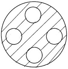
[0031] Such as Image 6 , Figure 7 As shown, it is the application of the present invention on a two-stroke in-cylinder direct-injection gasoline engine. The partition plate 1 is arranged between the combustion chamber 2 and the piston movement space 3. The diversion channel 4 in the space 3 has spiral ribs 16 on the wall surface of the diversion channel 4, which promotes disturbance when the gas passes through; the top opening 41 of the diversion channel faces the wall 21 of the combustion chamber, and the gas enters from the piston movement space 3 When the combustion chamber 2 impacts the combustion chamber wall 21 and flows along the combustion chamber wall 21, the combustion chamber wall 21 is cooled; the diversion channel 4 is distributed in a circular oblique manner on the partition plate 1, so that the gas enters the combustion chamber 2 from...

specific Embodiment 3

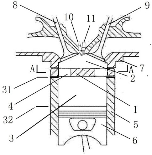
[0034] Specific embodiment three: the present invention is applied on the injection gasoline engine at the entrance of the four-stroke intake valve:

[0035] Such as Figure 8 As shown, it is the application of the present invention on the injection gasoline engine at the entrance of the four-stroke intake valve, the partition plate 1 is arranged between the combustion chamber 2 and the piston movement space 3, and the partition plate 1 is provided with a communication chamber 2 and The diversion channel 4 in the piston movement space 3 has a top opening 41 facing the wall 21 of the combustion chamber, and the diversion channel 4 is distributed in a circular and oblique manner on the partition plate 1 .

[0036] During the intake stroke, the exhaust valve 9 is closed, the intake valve 8 is opened, the piston 5 moves from the top dead center 31 to the bottom dead center 32, and the air or the mixture of air and recirculated combustion exhaust gas is sucked into the combustion c...

specific Embodiment 4

[0040] Specific embodiment four: the present invention is applied on four-stroke diesel engine:

[0041] Such as Figure 9 As shown, for the application of the present invention on a four-stroke diesel engine, the partition plate 1 is arranged between the combustion chamber 2 and the piston movement space 3, and the partition plate 1 is provided with a guide connecting the combustion chamber 2 and the piston movement space 3. The flow channel 4 has spiral convex ribs 16 on the wall of the flow guide channel 4, which promotes disturbance when the gas passes through; the top opening 41 of the flow guide channel faces the combustion chamber wall 21, and when the gas enters the combustion chamber 2 from the piston movement space 3 Impact the wall 21 of the combustion chamber and flow along the wall 21 of the combustion chamber to cool the wall 21 of the combustion chamber; The inner macroscopically has a vortex shape.

[0042] During the intake stroke, the exhaust valve 9 is clo...


PUM


Abstract

The invention relates to a method for improving the efficiency of an engine. An engine is arranged, a partition plate is arranged between a combustion chamber of the engine and a piston motion space, and a flow guide channel communicated with the combustion chamber and the piston motion space is arranged on the partition plate. The flow guide channels are annularly and obliquely distributed on the partition plate, and openings in the tops of the flow guide channels face the wall face of the combustion chamber. Gas forms a specific flow field after passing through the flow guide channel, combustible mixed gas is only located in the combustion chamber in combination with fuel injection time control, and the piston motion space is filled with air or non-combustible mixed gas formed by mixing air and recycled waste gas. A non-combustible gas heat insulation layer can be formed near the wall face of the combustion chamber in the process that the piston presses gas to enter the combustion chamber, stratified combustion and lean combustion can be achieved for a gasoline engine by combining ignition time control, the combustion efficiency is improved, heat conduction loss is reduced, and therefore the efficiency of the engine is improved.

Description

technical field [0001] The invention relates to an engine, in particular to a method for improving engine efficiency. Background technique [0002] The gas flow field in the engine cylinder plays a key role in the combustion efficiency and heat conduction loss. At present, the establishment of the gas flow field in the engine cylinder is mainly realized by the shape design of the piston top, the shape design of the combustion chamber, the setting of the deflector on the side of the intake valve, and the setting of the auxiliary combustion chamber. The design and verification process of this method is complicated, and Unable to achieve satisfactory results. Contents of the invention [0003] The technical problem to be solved by the invention is to provide a method for improving engine efficiency. [0004] The technical solution for solving the above-mentioned technical problems is: a method for improving engine efficiency, comprising the engine, the piston reciprocating ...

Claims


Application Information

Patent Timeline
Patent Type & Authority Applications(China)
IPC IPC(8): F02B23/08F02B23/02F02B23/10
CPCF02B23/08F02B23/101F02B23/02Y02T10/12
Inventor 臧晓辉刘闽春樊宸均张明钦黄彩鲜张建春
Owner LIUZHOU VOCATIONAL & TECHN COLLEGE
Why Eureka
Try Eureka