
A vibrating cavity waste incinerator

A waste incinerator, vibration technology, applied in the direction of incinerator, combustion type, combustion method, etc., can solve the problem of low efficiency of waste incineration, achieve convenient incineration, and improve the effect of combustion support

Active Publication Date: 2020-08-21
徐海军
View PDF9 Cites 0 Cited by
  • Summary
  • Abstract
  • Description
  • Claims
  • Application Information

AI Technical Summary

Problems solved by technology

[0004] In order to make up for the deficiencies in the prior art, the present invention proposes a vibrating furnace cavity garbage incinerator, which is mainly used to solve the problem of low efficiency of garbage incineration when the existing garbage incinerator burns garbage

Method used


Image

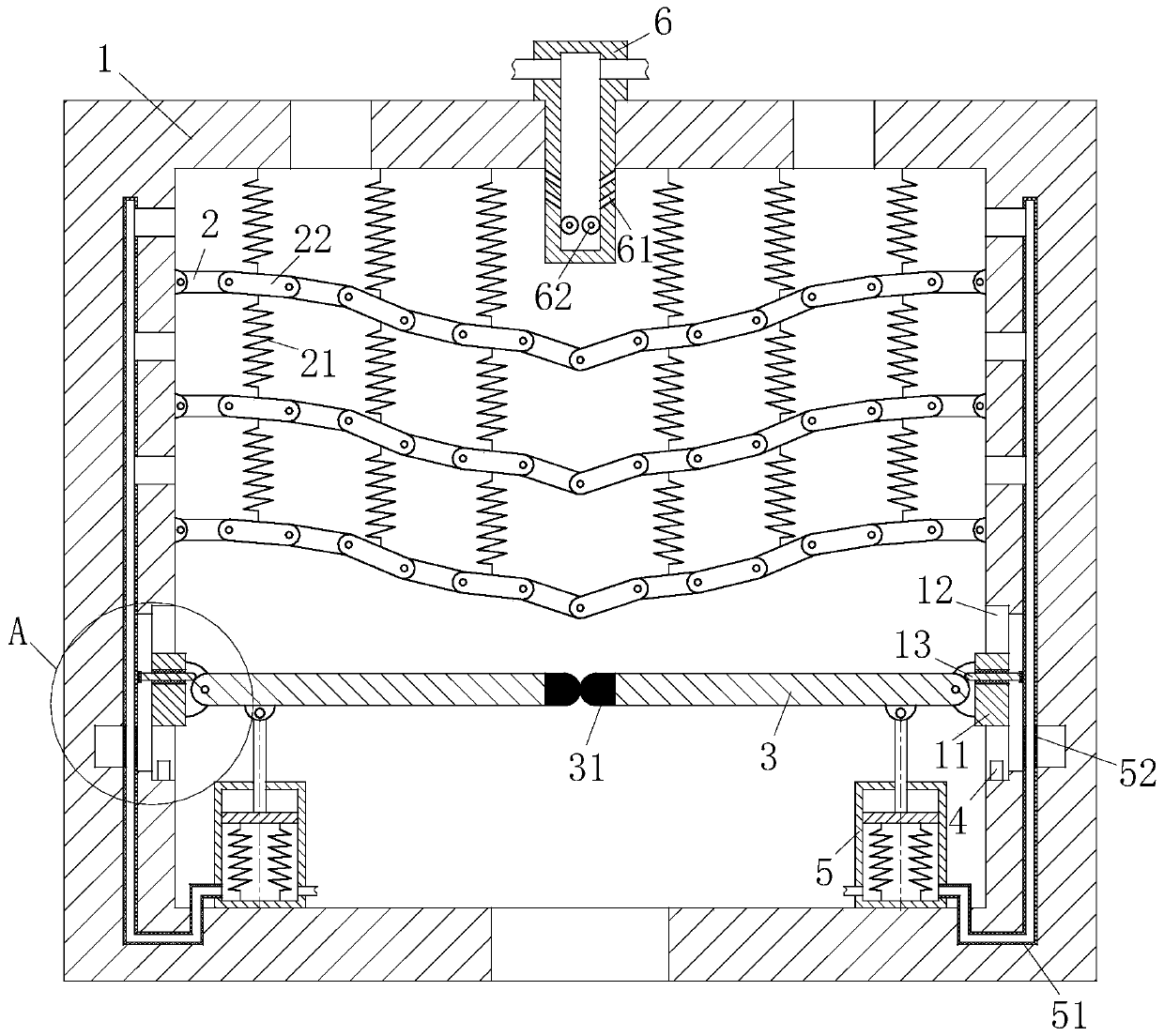
  • A vibrating cavity waste incinerator
  • A vibrating cavity waste incinerator
  • A vibrating cavity waste incinerator

Examples


Embodiment Construction

[0020] In order to make the technical means, creative features, goals and effects achieved by the present invention easy to understand, the present invention will be further described below in conjunction with specific embodiments.

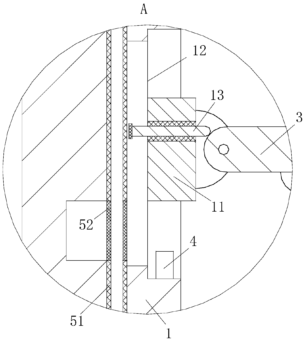
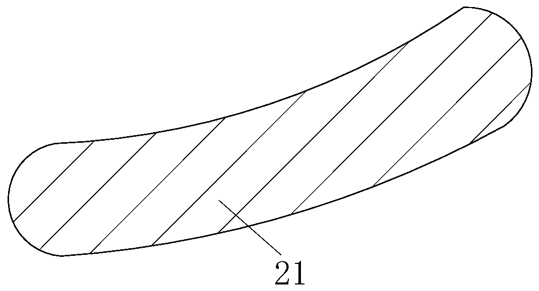
[0021] Such as Figure 1 to Figure 3As shown, a kind of vibrating furnace chamber garbage incinerator according to the present invention includes a furnace body 1, a plurality of fire grates 2 are arranged above the furnace body 1, and the holes on the top fire grate 2 are larger than the bottom fire grate 2 The holes on the fire grate 2 are provided with a combustion-supporting spring 21, and a combustion-supporting block is provided on the combustion-supporting spring 21, and the combustion-supporting block is used to promote the incineration of garbage; the top of the furnace body 1 is provided with a feed port, The bottom of the furnace body 1 is provided with a discharge port, and the left and right inner walls of the furnace body 1 are symme...


PUM


Abstract

The invention belongs to the technical field of garbage incinerators, and particularly relates to a vibration type furnace chamber garbage incinerator. The vibration type furnace chamber garbage incinerator comprises a furnace body, a plurality of fire grates are arranged above the furnace body, combustion-supporting springs are among the fire grates, and combustion-supporting blocks are arrangedon the combustion-supporting springs; sliding grooves for mounting sliding blocks are symmetrically arranged on the left inner wall and the right inner wall of the furnace body, sealing plates are correspondingly hinged to the opposite ends of the sliding blocks, electromagnets are arranged at the end parts of the sealing plates, and travel switches are arranged at the lower ends of the sliding grooves; and the lower surfaces of the sealing plates are hinged to piston rods of two air cylinders which are symmetrically arranged on a bottom plate of the furnace body left and right, springs are arranged between pistons of the air cylinders and inner bottom plates of the air cylinders, air outlets of the air cylinders are connected with air outlet pipes, the upper ends of the air outlet pipes penetrate into the furnace wall of the furnace body and communicate with cavities formed among the fire grates through a channel formed above the furnace body, the air outlets of the air cylinders areprovided with one-way valves with a one-way air outlet function, air inlets of the air cylinders are provided with one-way valves with a one-way air inlet function, the air inlets of the air cylindersare connected through air inlet pipes, and the other ends of the air inlet pipes are positioned at the top of the furnace body.

Description

technical field [0001] The invention belongs to the technical field of garbage incinerators, in particular to a vibrating cavity garbage incinerator. Background technique [0002] Garbage disposal has always been a major environmental issue of concern all over the world. Traditional waste disposal methods mainly include landfill and incineration. Landfilling will take up a lot of valuable land resources and pollute the environment at the same time, so this simple treatment method is basically no longer used. Compared with landfill disposal, waste incineration is a better disposal method. Through incineration, not only the volume of garbage is greatly reduced, but also the heat generated by incineration can be used to generate electricity and heat, so as to achieve the purpose of energy reuse. Therefore, incineration technology has become a kind of waste treatment technology commonly used at home and abroad. [0003] The application and development of waste incineration t...

Claims


Application Information

Patent Timeline
Patent Type & Authority Patents(China)
IPC IPC(8): F23G5/00F23G5/44F23G5/50
Inventor 虞刚崔雪柯谢响玲
Owner 徐海军
Learn More