Cyclone separation device of dust collector

A technology of a cyclone separation device and a vacuum cleaner, which is applied to suction filters and other directions, can solve the problems of large diameter and inability to use a cyclone separation device, etc., and achieve the effect of height reduction

Active Publication Date: 2007-07-18
ECOVACS ROBOTICS (SUZHOU ) CO LTD
View PDF2 Cites 47 Cited by
  • Summary
  • Abstract
  • Description
  • Claims
  • Application Information

AI Technical Summary

Problems solved by technology

Although such an improvement has reduced the height of the entire device to a certain extent, the diameter of this structure is very large, and many vacuum cleaners cannot use this short and fat cyclone separation device when designing their shapes.

Method used


Image

  • Cyclone separation device of dust collector
  • Cyclone separation device of dust collector
  • Cyclone separation device of dust collector

Examples


Embodiment 1

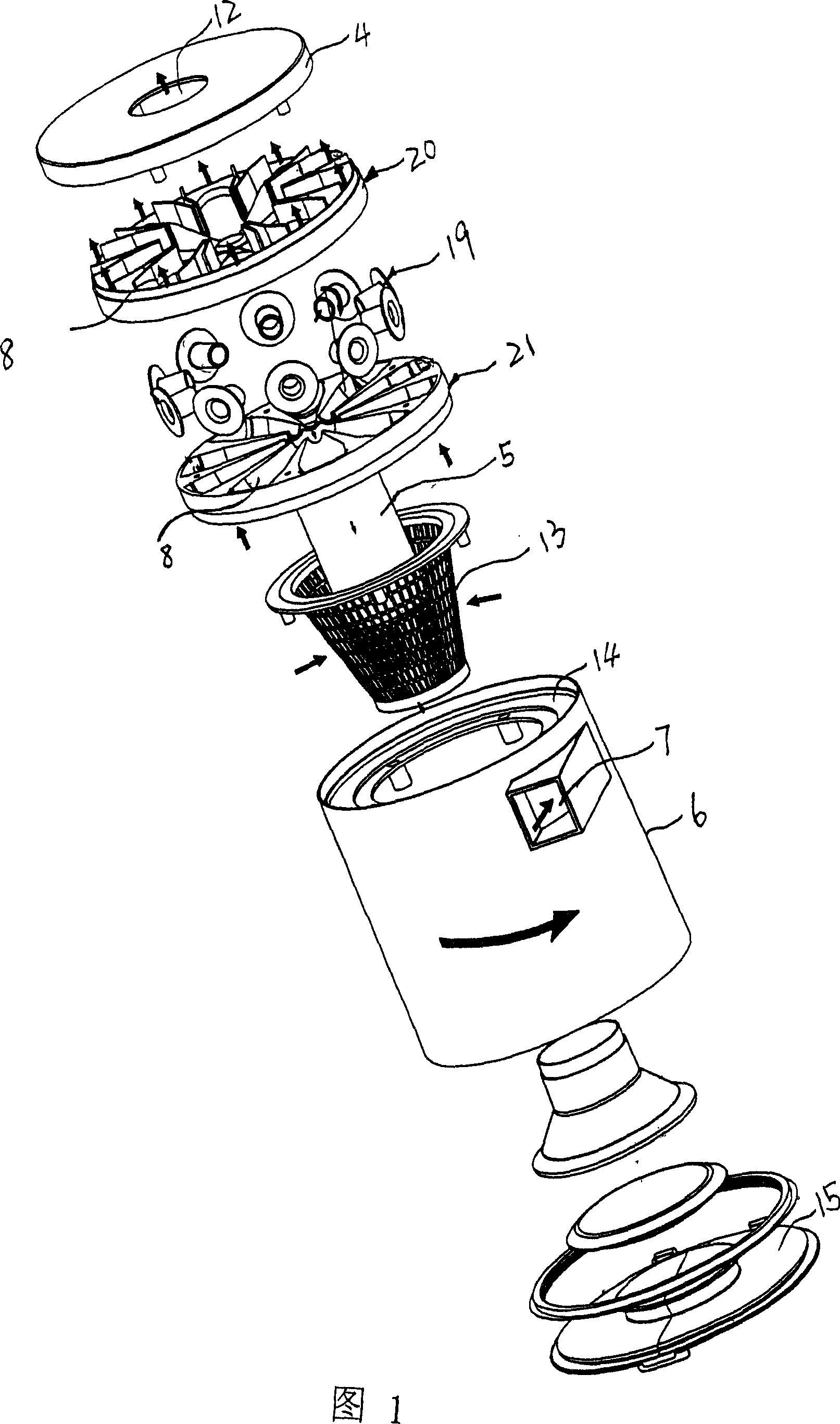
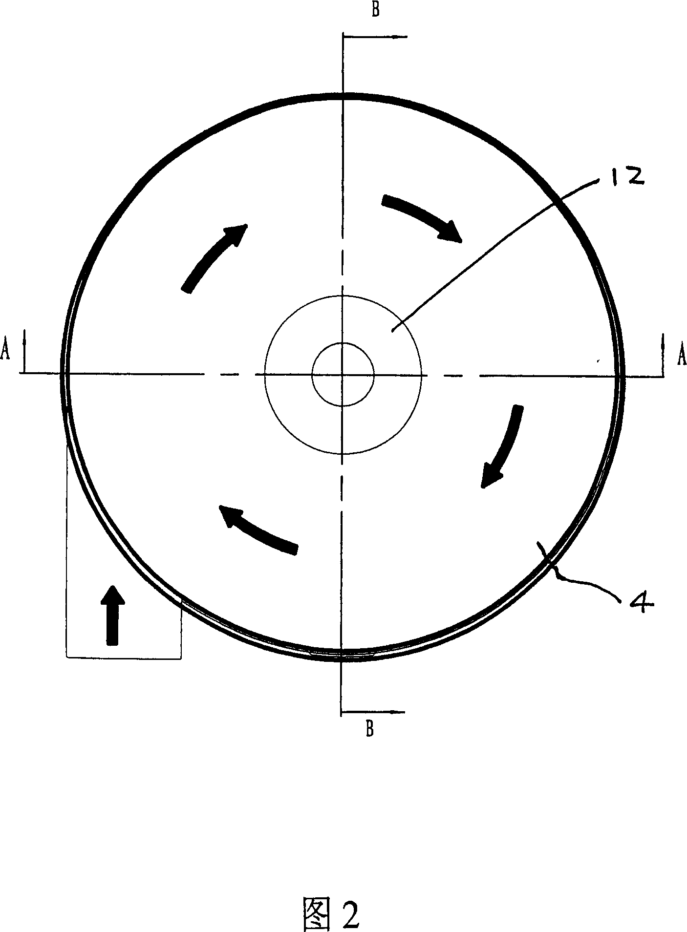
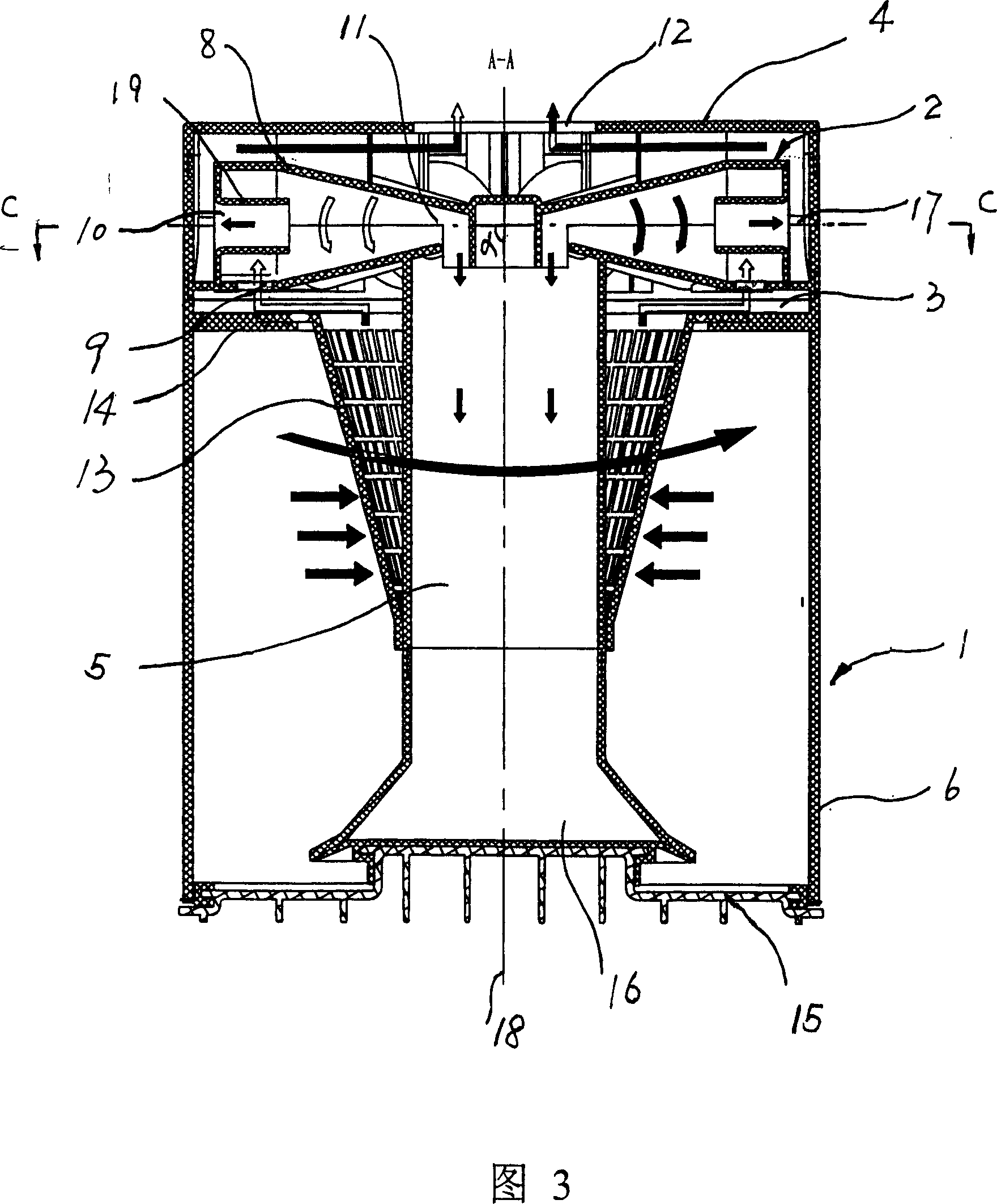
[0028] As shown in Figures 1 to 5, the cyclone separation device of the vacuum cleaner includes an upstream cyclone separation device 1 and a downstream cyclone separation device 2. The upstream cyclone separation device 1 and the downstream cyclone separation device 2 are connected through a gas channel 3, so The upstream cyclone separation device 1 has a first cyclone barrel 6, and the downstream cyclone separation device 2 includes 10 second cyclone barrels 8 in which a plurality of second cyclone barrels 8'are arranged side by side. Each of the downstream cyclone separation devices 2 It is arranged lying down above the upstream cyclone separator 1. Said lying is full lying, that is, the included angle α between the axis 17 of the second cyclone barrel 8 and the axis 18 of the first cyclone barrel 6 is 75 degrees to 125 degrees, which is basically full Lying down.

[0029] In this embodiment, the included angle a between the axis 17 of the second cyclone barrel 8 and the axis 1...

Embodiment 2

[0036] As shown in Figures 6 and 7, the cyclone separation device of the vacuum cleaner includes an upstream cyclone separation device 1'and a downstream cyclone separation device 2'. The upstream cyclone separation device 1'and the downstream cyclone separation device 2'pass between The gas passage 3'is in communication, the upstream cyclone separation device 1'has a first cyclone barrel 6', the downstream cyclone separation device 2'includes 8 second cyclone barrels 8', and the respective downstream cyclone separation devices 2'lie It is installed above the upstream cyclone separation device 1'. The lying is half-lying, that is, the angle α between the axis 17' of the second cyclone barrel 8'and the axis 18' of the first cyclone barrel 6'is 15 degrees to 165 degrees Is half-lying.

[0037]In this embodiment, the included angle a between the axis 17' of the second cyclone barrel 8'and the axis 18 of the first cyclone barrel 6'is 135 degrees, and the first cyclone barrel 6' A firs...


PUM


Abstract

A cyclone separator system for cleaner is composed of an upstream cyclone separator with the first cyclone cylinder, a horizontal downstream cyclone separator above said upstream cyclone separator and with at least one the second cyclone cylinder, and a gas channel between said two cyclone separators. It has lower height.

Description

Technical field [0001] The invention relates to a device for separating particles from a fluid airflow, in particular to a cyclone separation device of a vacuum cleaner that separates particles such as dust from air and fluid. Background technique [0002] The cyclone separator is a device that separates gas and dust from the centrifugal force generated by the high-speed rotating airflow in the cyclone barrel. In the prior art, a two-stage cyclone separation device is usually connected in series, so that the dust-containing air passes through the upstream cyclone separation device to preliminarily filter out large particles of dust, and then the downstream cyclone separation device further filters the dust particles, so as to achieve air purification. effect. [0003] However, the structure of the two-stage cyclone separation device in series will increase the cleaning efficiency while also increasing the volume of the device, which brings inconvenience to the user's operation; t...

Claims


Application Information

Patent Timeline
Patent Type & Authority Applications(China)
IPC IPC(8): A47L9/16
Inventor 钱东奇
Owner ECOVACS ROBOTICS (SUZHOU ) CO LTD
Why Eureka
Try Eureka