
Fixing clamp for shaft sleeve

A technology for fixing fixtures and shaft sleeves, which is applied in the direction of clamping, positioning devices, and manufacturing tools. It can solve the problems of shaft and sleeve locking, high scrap rate, and low efficiency, so as to ensure coaxiality and improve the authenticity rate. , The effect of convenient clamping

Active Publication Date: 2007-07-18
SUZHOU ZHOUYANG PRECISION MACHINERY TECH CO LTD
View PDF0 Cites 11 Cited by
  • Summary
  • Abstract
  • Description
  • Claims
  • Application Information

AI Technical Summary

Problems solved by technology

If the inner hole and the outer diameter of the bushing are not coaxial, it will cause the shaft and the bushing to lock during high-speed operation of the sewing machine, or the bushing and the shaft will rotate together, so that the sewing machine cannot operate normally; if the cylindricity and roundness of the inner hole The error of the degree is greater than 0.002mm. When the sewing machine is running at high speed, there will be point contact between the shaft and the shaft sleeve, which will accelerate the wear of the shaft sleeve and shaft, and directly affect the service life of the sewing machine.
The fixture used to fix the bushing in the prior art usually has a plurality of movable jaws. During loading and unloading, these jaws must be adjusted separately to move and clamp the workpiece. This kind of fixture is cumbersome to operate , Inefficiency, and because of the sequential action of multiple jaws, it is easier to clamp the parts, resulting in large errors in the roundness, cylindricity and coaxiality of the inner hole of the processed product, so the scrap rate is high

Method used


Image

  • Fixing clamp for shaft sleeve
  • Fixing clamp for shaft sleeve
  • Fixing clamp for shaft sleeve

Examples


Embodiment Construction

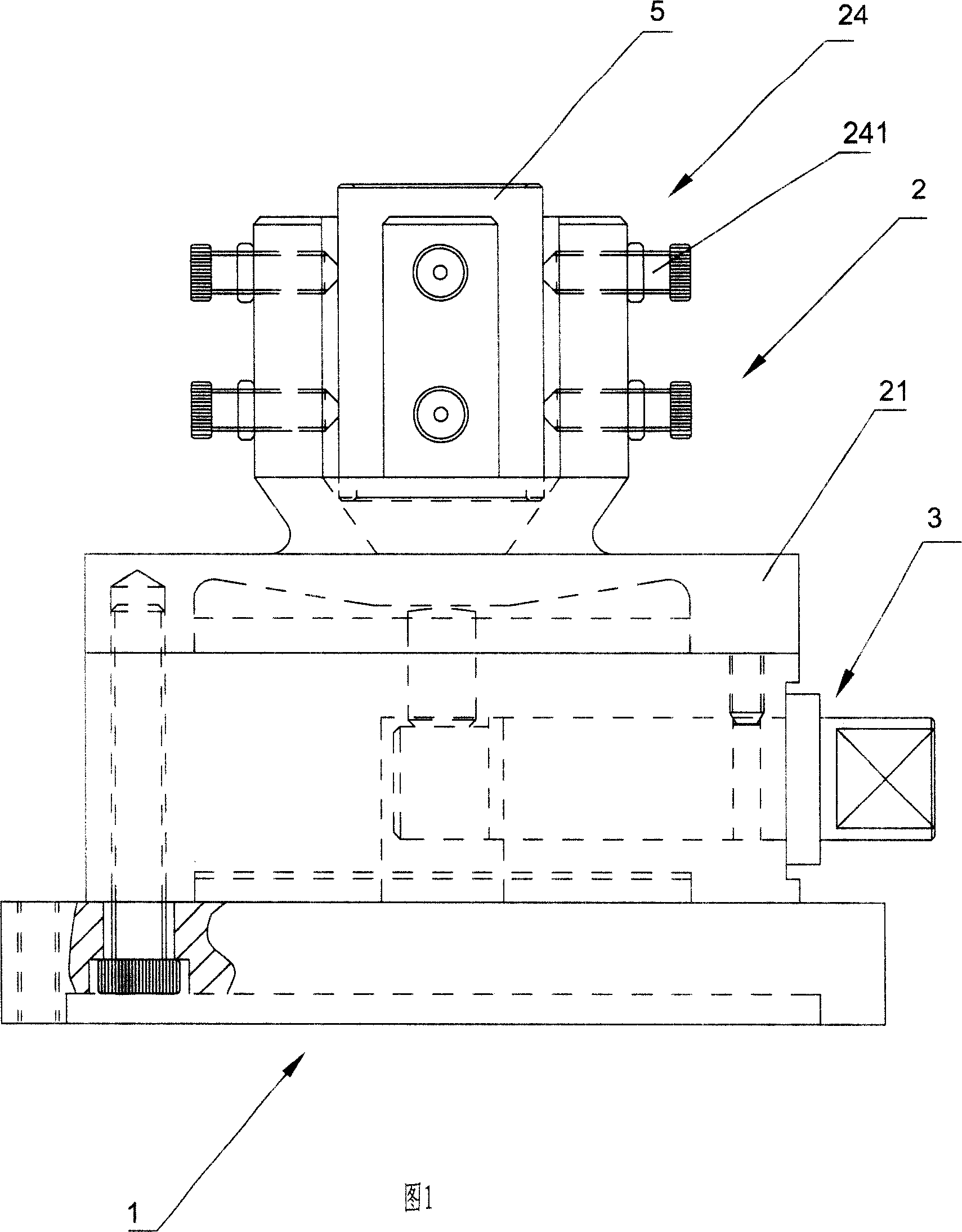
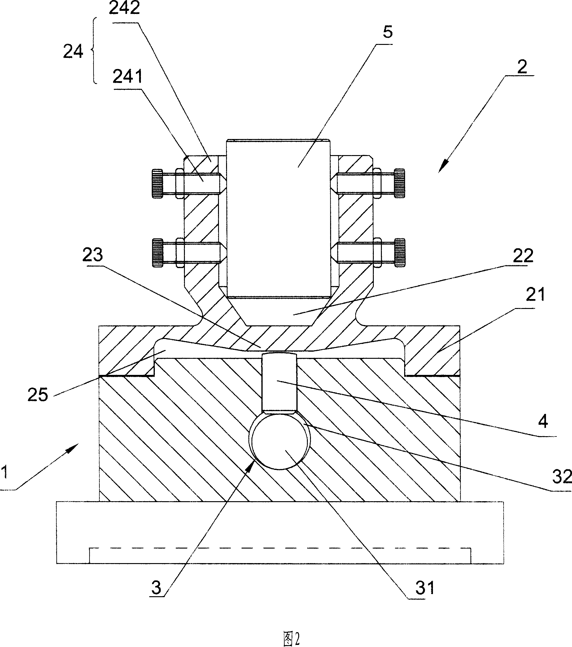
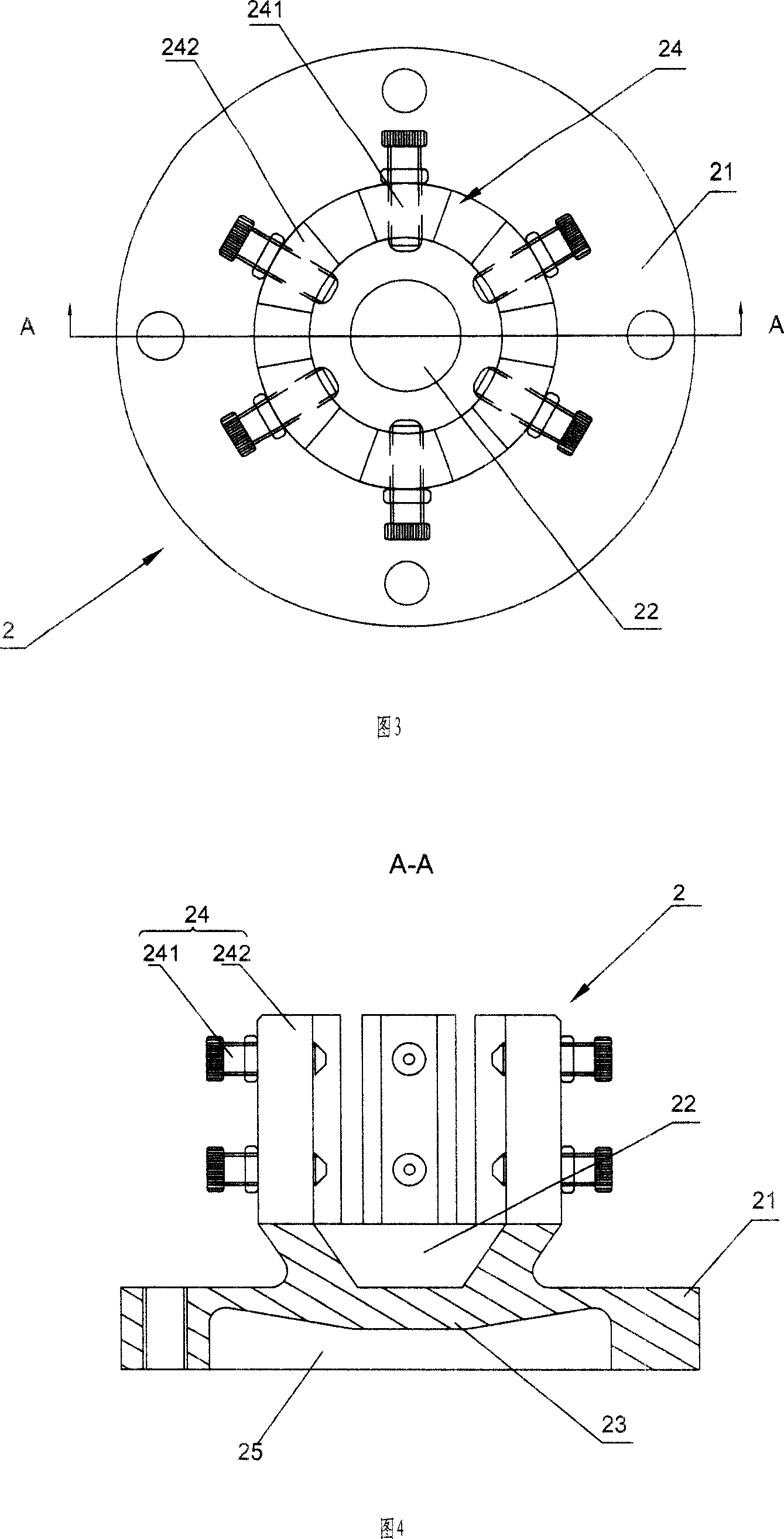
[0015] Referring to accompanying drawings 1 to 5, a shaft sleeve fixing fixture includes a seat body 1, a clip body 2 fixedly arranged above the seat body 1, and is located between the seat body 1 and the clip body 2 and can be positioned along its own axis. The push rod 4 that moves in the direction of the heart line. Wherein, the clip body 2 includes a base 21 and a plurality of claws 24 arranged on the base 21 for clamping the workpiece 5, and the upper part of the base 21 is provided with a tapered hole 22 whose longitudinal section is truncated and inverted conical (in this specification The described "up", "down" positional relationship corresponds to the upper and lower positional relationship shown in accompanying drawing 1), the axis line of the taper hole 22 coincides with the axis line of the ejector rod 4, and a plurality of claws 24 are evenly distributed on a circle, and the center of the circle is located on the axis of the tapered hole 22 . A cavity 25 is dug ...


PUM


Abstract

The present invention relates to a shaft sleeve retaining clamp. It includes seat body, clamp body and ejector pin positioned between above-mentioned seat body and clamp body. Said clamp body includes base seat and several jaws, on the upper portion of said base seat a conical hole is cut, said several jaws are uniformly distributed on the periphery of said conical hole, the lower portion of said base seat has a hollow cavity, and the base seat between the conical hole and hollow cavity is formed into an elastic portion, the upper end portion of said ejector pin is tightly supported on the elastic portion. Besides, said invention also provides its working principle and concrete operation method.

Description

technical field [0001] The invention relates to a fixture for fixing shaft sleeve parts, in particular to a clamp for fixing the shaft sleeve when machining the inner hole of the shaft sleeve. Background technique [0002] Shaft sleeve parts are widely used in industrial sewing machines, and the consumption is also large. The coaxiality, roundness and cylindricity of the inner hole processing have a great influence on the operation of the sewing machine. If the inner hole and the outer diameter of the bushing are not coaxial, it will cause the shaft and the bushing to lock during high-speed operation of the sewing machine, or the bushing and the shaft will rotate together, so that the sewing machine cannot operate normally; if the cylindricity and roundness of the inner hole The error of the degree is greater than 0.002mm. When the sewing machine is running at high speed, there will be point contact between the shaft and the shaft sleeve, which will accelerate the wear of th...

Claims


Application Information

Patent Timeline
IPC IPC(8): B23Q3/00B23B31/173B23B31/175
Inventor 葛长存马富祥
Owner SUZHOU ZHOUYANG PRECISION MACHINERY TECH CO LTD
Learn More