Operating mechanism of automobile hand brake

A control mechanism and hand brake technology, applied in the field of automobile hand brake control mechanism, can solve problems such as occurrence of danger, and achieve the effects of low cost, avoidance of danger and simple structure

Inactive Publication Date: 2007-07-18
CHERY AUTOMOBILE CO LTD
View PDF0 Cites 5 Cited by
  • Summary
  • Abstract
  • Description
  • Claims
  • Application Information

AI Technical Summary

Problems solved by technology

The disadvantage of this structure is: no matter whether there is an intention to release the hand brake, as long as the force acting on the button is large enough, the hand brake will be released. Pressing the handbrake button out of curiosity will cause danger and cause an accident

Method used


Image

  • Operating mechanism of automobile hand brake
  • Operating mechanism of automobile hand brake

Examples


Embodiment Construction

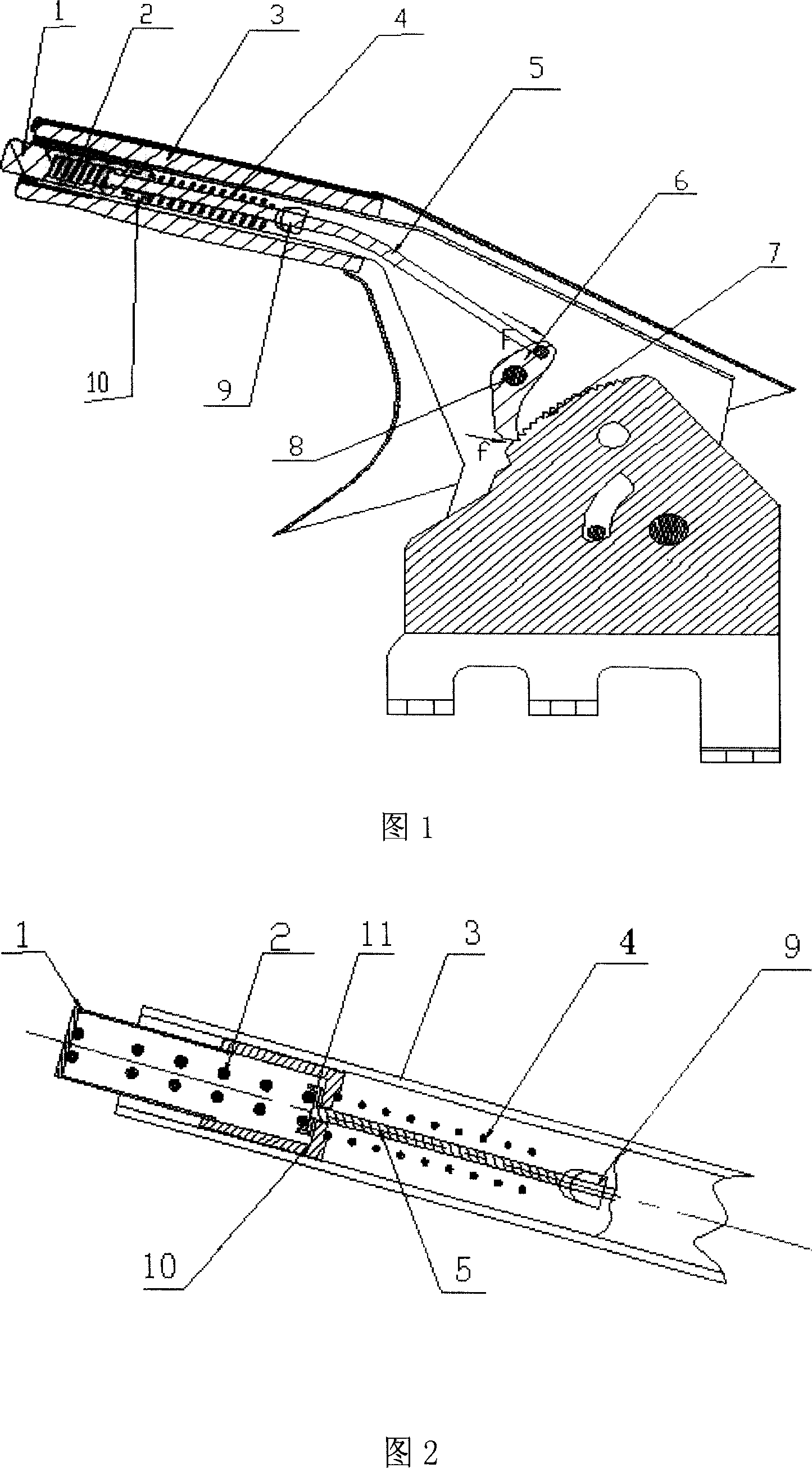
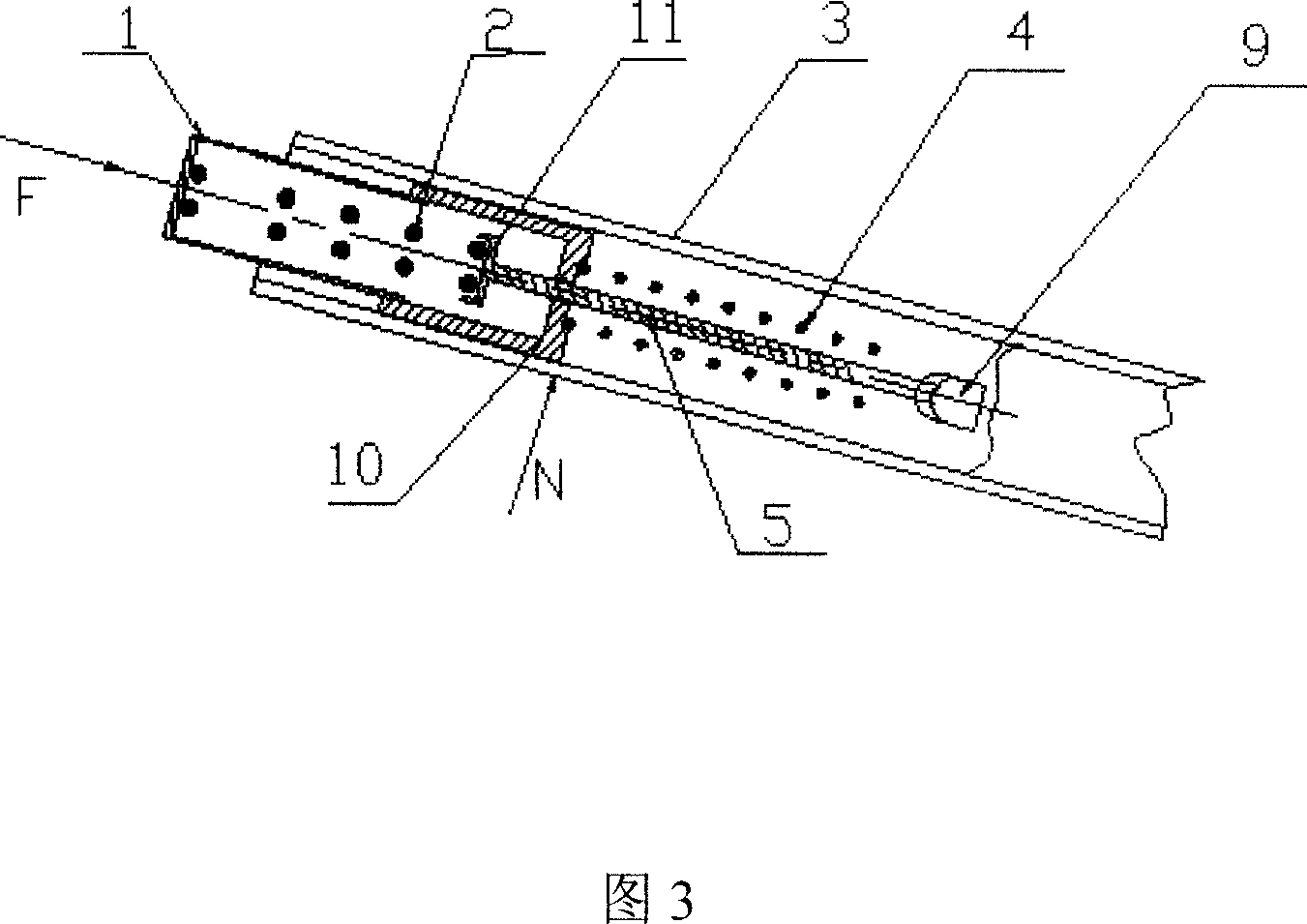
[0013] As shown in Fig. 1 and Fig. 2, the automobile hand brake control mechanism of the present invention comprises a handle 3, a button 1, a hand brake push rod 5, a ratchet 6 and a toothed plate 7 with ratchet teeth, and the toothed plate 7 is fixed on the vehicle body floor , the ratchet 6 is fixed on the rear end of the handle 3 by the rotating shaft 8, and its pawl cooperates with the ratchet on the tooth plate 7. The hand brake push rod 5 is installed in the through hole in the middle of the handle 3, and the end of the hand brake push rod 5 Hinged with the ratchet 6, the through hole of the handle 3 is provided with a return spring 4 that makes the hand brake push rod 3 return to the front end of the handle and a spring clamp 9 that is fixed in the handle 3 to position the spring, and the hand brake push rod The front end of 5 has a sliding spring seat 10 that is set on the hand brake push rod and acts on the return spring 4; the front end of the hand brake push rod 5 h...


PUM


Abstract

The present invention discloses an automobile hand-brake control mechanism. Said hand-brake control mechanism includes the following several portions: handle, push button, hand-brake push lever, ratchet wheel and toothed plate with ratchet, reset spring and spring seat, and energy-storing spring, etc. said invention also provides the connection mode of all the above-mentioned portions, and the working principle of said hand-brake control mechanism and its concrete operation method.

Description

technical field [0001] The invention relates to an automobile hand brake operating mechanism, in particular to an automobile hand brake operating mechanism which can prevent misoperation from releasing the hand brake. Background technique [0002] At present, the general hand brake control mechanism on the automobile includes a handle, a button, a hand brake push rod, a ratchet and a toothed plate with ratchet teeth. The pawl cooperates with the ratchet on the gear plate. The button and the hand brake push rod are installed in the through hole in the middle of the handle. The return spring that the bar returns to the front end of the handle is fixed with a spring holder for positioning the spring in the handle. When you press the button with your finger, the button will drive the hand brake push rod to move backward and compress the return spring. The teeth disengage to complete the release action of the hand brake. The disadvantage of this structure is: no matter whether...

Claims


Application Information

Patent Timeline
Patent Type & Authority Applications(China)
IPC IPC(8): B60T7/10
Inventor 兰维新庄海石
Owner CHERY AUTOMOBILE CO LTD
Why Eureka
Try Eureka