Rotary cup spinning device provided with drivable rotary cup

A technology of rotor spinning and rotor spinning, which is applied in the direction of continuous winding spinning machine, spinning machine, open-end spinning machine, etc., and can solve the problem of speed increase and other problems

Inactive Publication Date: 2007-07-18
RIETER INGOLSTADT GMBH
View PDF1 Cites 6 Cited by
  • Summary
  • Abstract
  • Description
  • Claims
  • Application Information

AI Technical Summary

Problems solved by technology

It is true that the prescribed measures are not...

Method used


Image

  • Rotary cup spinning device provided with drivable rotary cup

Examples


Embodiment Construction

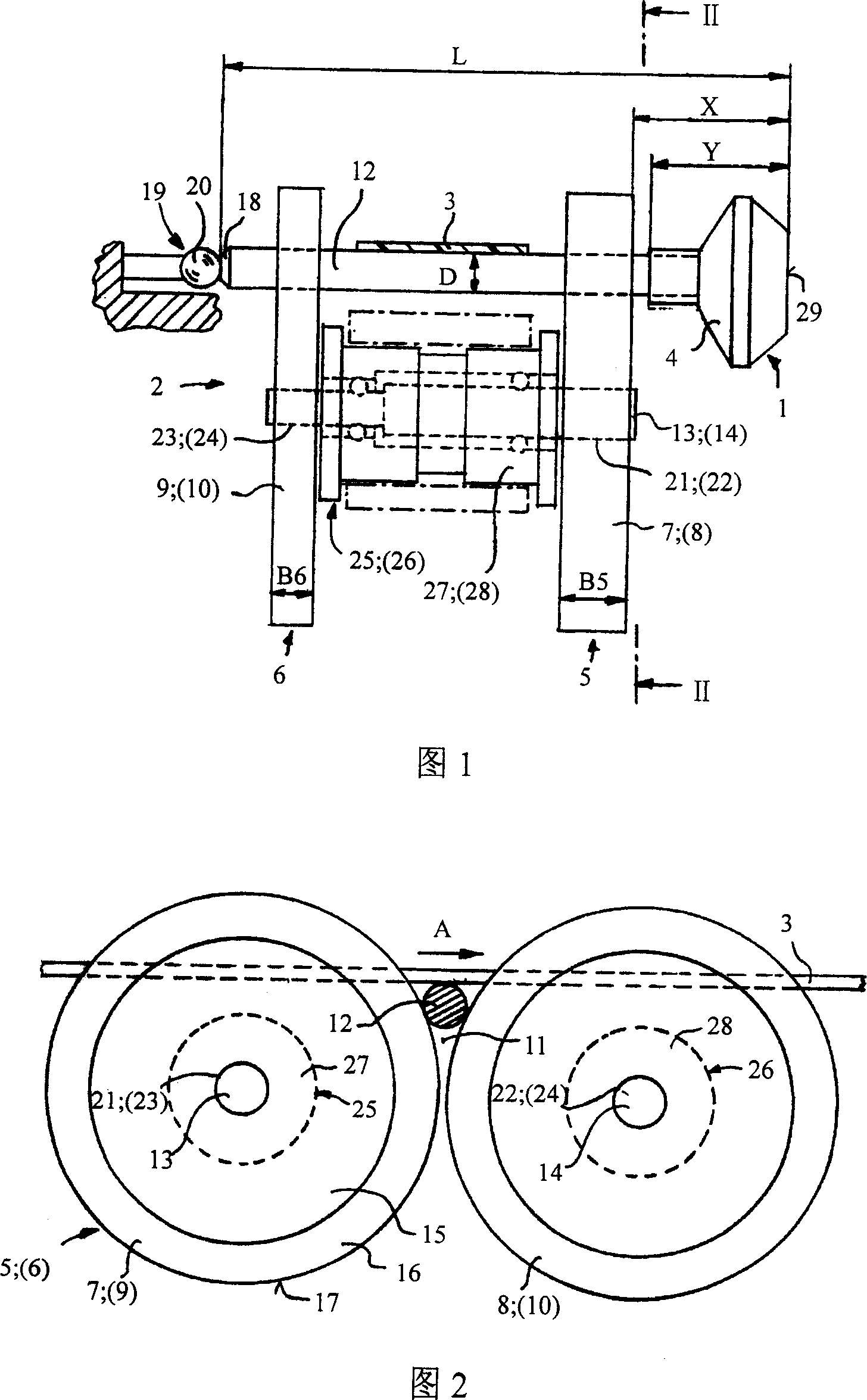
[0016] The rotor spinning device shown only partially in FIGS. 1 and 2 basically shows a rotor spinning device 1 , which is mounted in a support disk bearing 2 and can be driven by a tangential drive belt 3 . The rotor spinning 1 has a rotor disc 4 in which the actual yarn formation process takes place. Devices for adding individual yarns and for doffing the spun yarn from the rotor disc 4 are added to the rotor disc 4 in a manner not shown but known per se.

[0017] The support disc bearing 2 comprises two support disc pairs 5 and 6 with two support discs 7 and 8 and 9 and 10 each. The pair of support disks 5 and 6 forms a wedge-shaped gap 11 in which a rotor shaft 12 of a rotor spinning 1 fastened to the twist ring disk 4 is radially supported. The supporting disks 7 and 9 and 8 and 10 , which are respectively located on the side next to the rotor shaft 12 , are arranged on a common shaft 13 or 14 .

[0018] The structures of the support discs 7, 8, 9 and 10 are basically ...


PUM


Abstract

A rotor spinning device includes a drivable rotor-spun having a rotor pan and a rotor shaft. The rotor shaft of the rotor-spun is supported on at least a radial bearing in high rotary speed. An overhanging part is provided on the rotor-spun, which is less than 29 mm measured from an anterior border of the rotor pan to a head of the radial bearing. The rotor-spun can be driven by a tangential transmission belt near the rotor shaft. Product of the overhanging part (mm) and diameter (mm) of the rotor shaft within a range of the tangential transmission belt is less than 250. In addition, it is predefined that the rotor shaft is radially supported on a pair of angular interstices of a pair of supporting discs while the interstices are separated for a certain distance in an axis direction, wherein, width of the supporting disc towards to the pair of supporting discs of the rotor pan is larger than that of the supporting disc opposite to the pair of supporting discs of the rotor pan.

Description

technical field [0001] The invention relates to a rotor spinning device with a driveable rotor spinning device, wherein the rotor spinning has a rotor disk and a rotor shaft, and the rotor spinning is supported on at least On a radial bearing, moreover, the rotor has an overhang measured from the front edge of the rotor disc to the start of the radial bearing. Background technique [0002] For rotor spinning with this type of rotor spinning setup, 180,000min is being devoted in practice today -1 order of magnitude of speed. The speed that can be achieved by rotor spinning is basically the critical speed as the standard speed, because considering safety, the operating speed must always be below the critical speed. [0003] Measures for increasing the critical speed are known from DE 19729941 A1. For example, it is stipulated that the length of the rotor shaft should be approximately ten times its diameter. It is true that the prescribed measures are not enough to increase...

Claims


Application Information

Patent Timeline
IPC IPC(8): D01H4/08D01H4/12
CPCD01H4/12
Inventor E·许勒尔W·措特M·布尔歇特M·劳尔M·库布勒G·豪格E·博克
Owner RIETER INGOLSTADT GMBH
Why Eureka
Try Eureka