Mainframe management system and method

A technology of management system and management method, which is applied in the field of chassis management system, can solve the problems of cost increase, increase of setting cost, inflexibility, etc., and achieve the effect of reducing cost and improving setting flexibility

Inactive Publication Date: 2007-07-18
INVENTEC CORP
View PDF0 Cites 12 Cited by
  • Summary
  • Abstract
  • Description
  • Claims
  • Application Information

AI Technical Summary

Problems solved by technology

However, the configuration of the main control end and the backup end are generally realized by hardware circuit design, so it is not flexible. Moreover, the main control end and the backup end belong to different architectur

Method used


Image

  • Mainframe management system and method

Examples


Embodiment

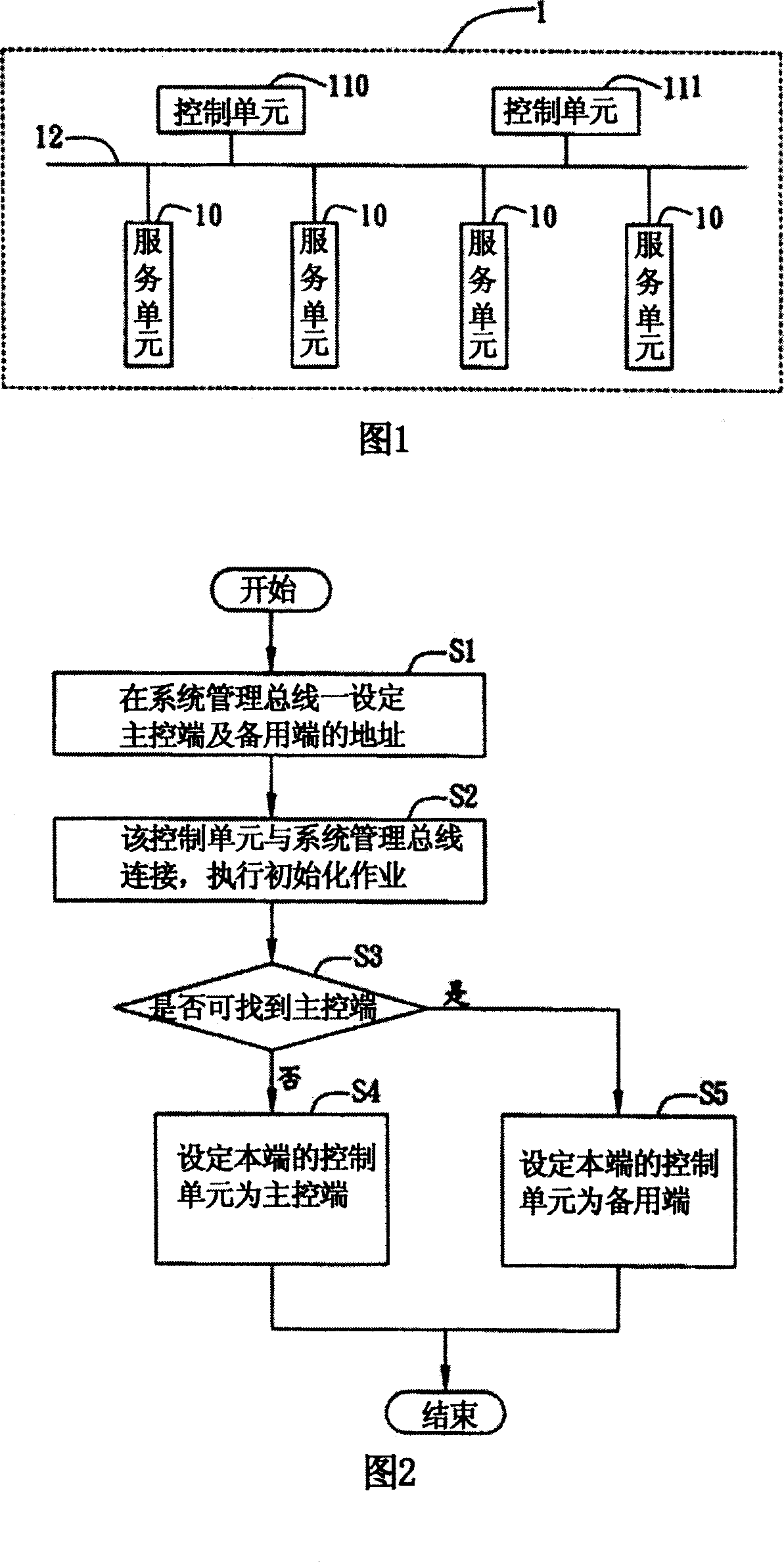
[0014] FIG. 1 is a schematic block diagram showing a chassis management system of the present invention. As shown in FIG. The service unit 10 , the first control unit 110 and the second control unit 111 establish a network connection relationship through the system management bus 12 . The chassis management system 1 of the present invention is applied in a blade server, and utilizes an intelligent platform management bus (Intelligent Platform Management Bus; IPMB), that is, the bus characteristic of a system management bus (System Management Bus, SM Bus) to set the master in the blade server. Control end and backup end.

[0015] The service unit 10 refers to a device that needs to be managed such as a KVM (Keyboard, Video, Mouse) module that provides data output / input processing or a plurality of blade motherboards that are located in a blade server; the first control The unit 110 and the second control unit 111 are used to manage the running status of all service units 10, f...


PUM


Abstract

A mainframe management system comprises at least one service unit, the first and the second control units for managing operation state of said service unit, system management bus for connecting service unit to the first and the second control units. The said management system can conveniently and quickly finalize the setting of master control end and spare control end on blade server.

Description

technical field [0001] The present invention relates to a chassis management system and method, in particular to a chassis management system and method for setting a master control terminal and a backup terminal of a blade server through a system management bus. Background technique [0002] Traditionally, more than 20 blade motherboards can be placed in the blade server chassis according to the needs. Since the blade server can densely build multiple motherboards and provide high processing performance, it has become a must for high-performance network systems. equipment. [0003] Generally, it monitors multiple blade mainboards installed inside the blade server, so one of the multiple blade mainboards is selected as the main control terminal, and the main control terminal is often connected to the network system as the communication between the blade server and the outside world. Pipeline, and when a problem occurs on the blade main board, the relevant problem information...

Claims


Application Information

Patent Timeline
IPC IPC(8): G06F11/16
Inventor 陈连埙王宗斌卢晓芬
Owner INVENTEC CORP
Why Eureka
Try Eureka