
Multi-screen display splicing controller

A splicing controller and multi-screen display technology, applied in static indicators, automatic power control, cathode ray tube indicators, etc., can solve the problems of not meeting high-definition display requirements, increasing image noise, poor stability, etc. Achieve the effect of meeting high-definition display requirements, strong anti-interference ability, and high stability

Active Publication Date: 2007-07-18
KONKA GROUP
View PDF0 Cites 46 Cited by
  • Summary
  • Abstract
  • Description
  • Claims
  • Application Information

AI Technical Summary

Benefits of technology

This technology solves problems by providing better performance without damaging images or adding unwanted noises during operation compared to previous methods such as analogue processors (APs). It also allows for independent control over its functioning while running at speeds faster than traditional systems like CPUs.

Problems solved by technology

The technical problem addressed in this patented text relates to improving large screen displays' performance while maintaining stable operation independent of their computers during data transmissions over networks such as internet or wireless communication channels.

Method used


Image

  • Multi-screen display splicing controller
  • Multi-screen display splicing controller

Examples


Embodiment Construction

[0023] The present invention will be further described below in conjunction with the accompanying drawings and embodiments.

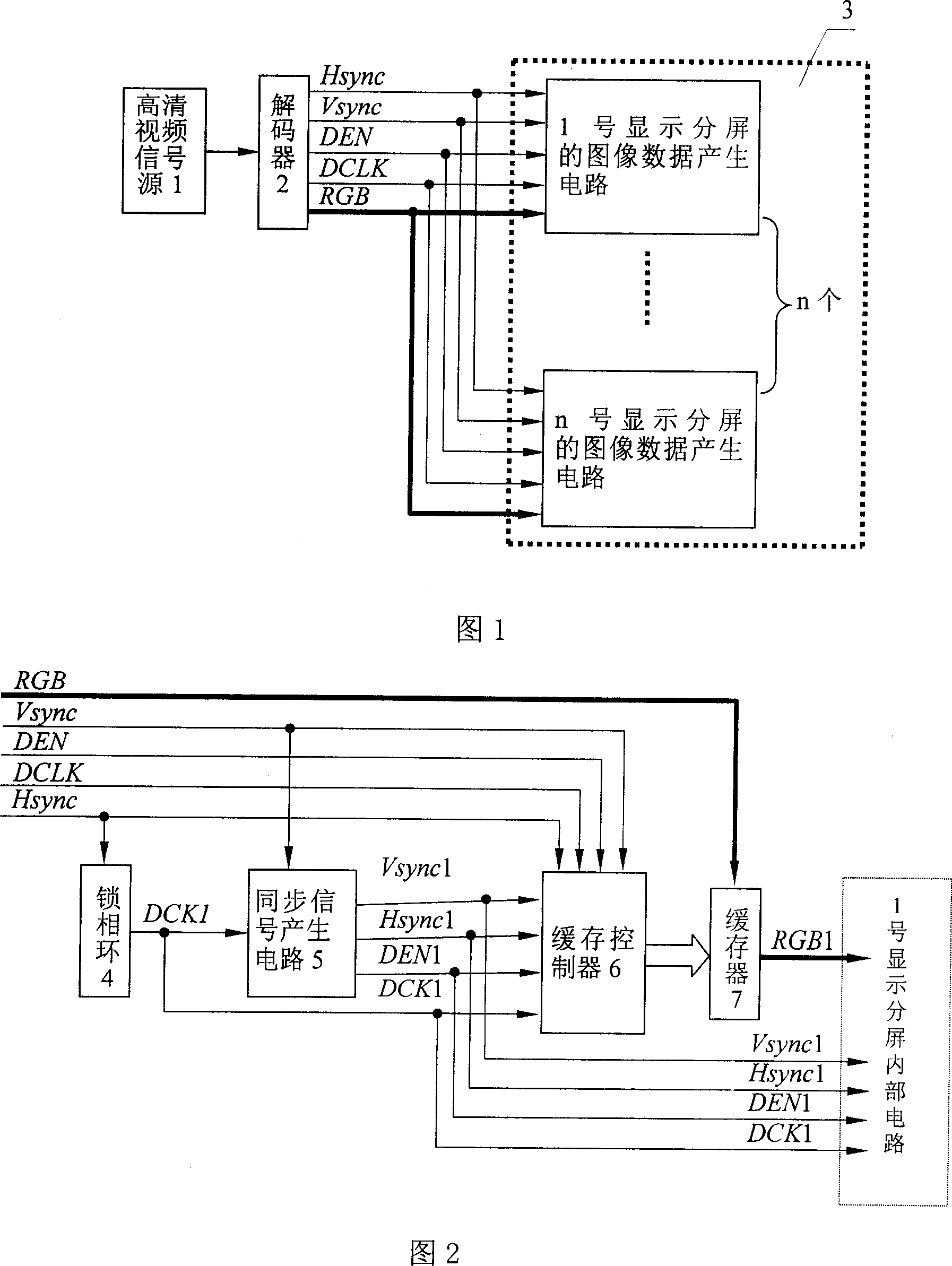
[0024] As shown in Figure 1, the multi-screen display splicing controller of the present invention includes: a high-definition video signal source 1 that produces high-definition or ultra-high-definition video signals; for decoding high-definition or ultra-high-definition video signals and output digital image signal groups The decoder 2; the display screen image data generation circuit 3 for receiving the digital image signal group; the display screen image data generation circuit 3 is composed of the image data generation circuit of No. 1 display split screen and the image of No. 2 display split screen The data generation circuit, ..., the maximum value is 64 display split-screen image data generation circuits are formed in parallel, and receive the signal output by the decoder. As a preferred embodiment, the high-definition video signal source adopts...


PUM


Abstract

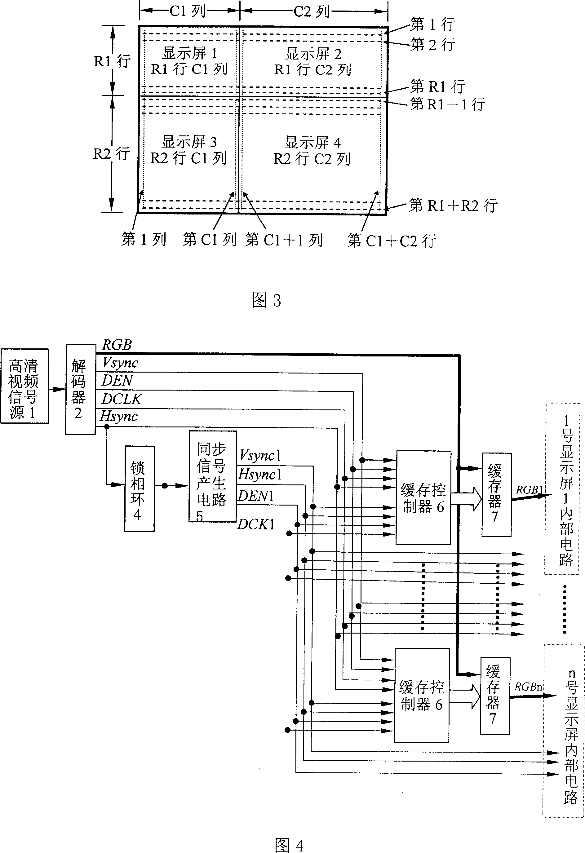
A splicing controller of multi-screen display consists of high definition video signal source and decoder. It is featured as outputting signal to display sub-screen image data generation circuit formed by phase-locked loop, synchronous signal generator, buffer storage controller, buffer storage and internal circuit of display sub-screen.

Description


Claims


Application Information

Patent Timeline
Owner KONKA GROUP
Learn More