Broadband single ridge waveguide broadside longitudinal seam standing-wave antenna

A single-ridge waveguide and wide-edge technology, which is applied in the direction of slot antenna, waveguide, antenna, etc., can solve the problems of not using widened bandwidth, increasing the thickness of the area array, and greatly affecting performance, so as to achieve easy port impedance matching and broaden the working bandwidth , processing simple effect

Inactive Publication Date: 2007-07-18
CHINA ELECTRONIC TECH GRP CORP NO 38 RES INST
View PDF0 Cites 28 Cited by
  • Summary
  • Abstract
  • Description
  • Claims
  • Application Information

AI Technical Summary

Problems solved by technology

[0007] In the early dual-polarized waveguide slot antenna arrays, both slotted waveguide arrays adopt the conventional design method, that is, the vertically polarized The narrow side of the waveguide is opened with inclined slots, and the horizontally polarized linear array is placed on the surface of the vertically polarized linear array, resulting in an increase in the thickness of the array and a great impact on performance
In addition, there is no measure to widen the bandwidth, and the working bandwidth is narrow

Method used


Image

  • Broadband single ridge waveguide broadside longitudinal seam standing-wave antenna
  • Broadband single ridge waveguide broadside longitudinal seam standing-wave antenna
  • Broadband single ridge waveguide broadside longitudinal seam standing-wave antenna

Examples


Embodiment 1

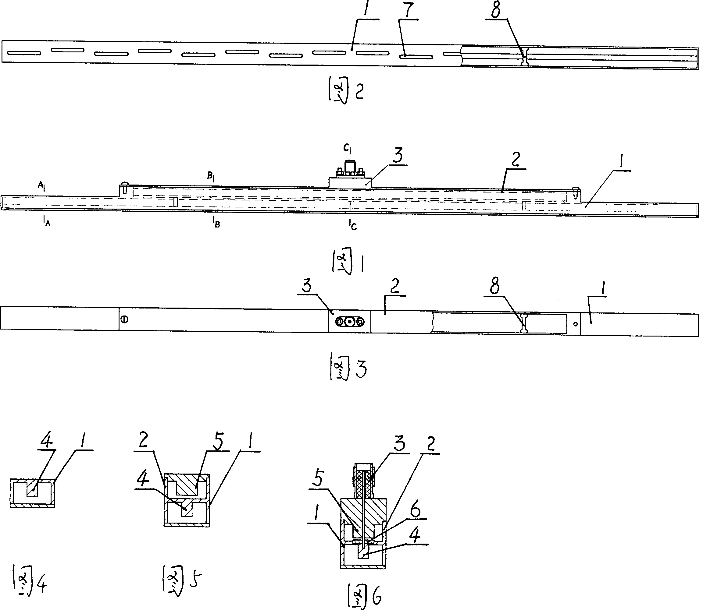
[0047] A broadband single ridge waveguide broadside longitudinal slot standing wave antenna includes a radiation waveguide 1, a feeding waveguide 2 and a coaxial connector 3, see Fig. 1, Fig. 2, Fig. 3, Fig. 4, Fig. 5 and Fig. 6.

[0048] Radiation waveguide 1 is staggered with longitudinal radiation slots 7 on both sides of the center line of the radiation side, and longitudinally divides the antenna array into two identical sub-arrays; the radiation slot length is 0.5312 wavelengths, and the slot width is much smaller than the slot length; between adjacent radiation slots The distance between the radiation slots is 0.5 waveguide wavelength, and the deviation of the radiation slot from the center line of the radiation ridge waveguide is 0.0576 wavelength; the sub-array is short-circuited at a distance of 0.25 waveguide wavelength from the last radiation slot; The slot performs energy coupling, and the coupling feeding waveguide terminal is short-circuited at a distance of 0.5 ...

Embodiment 2

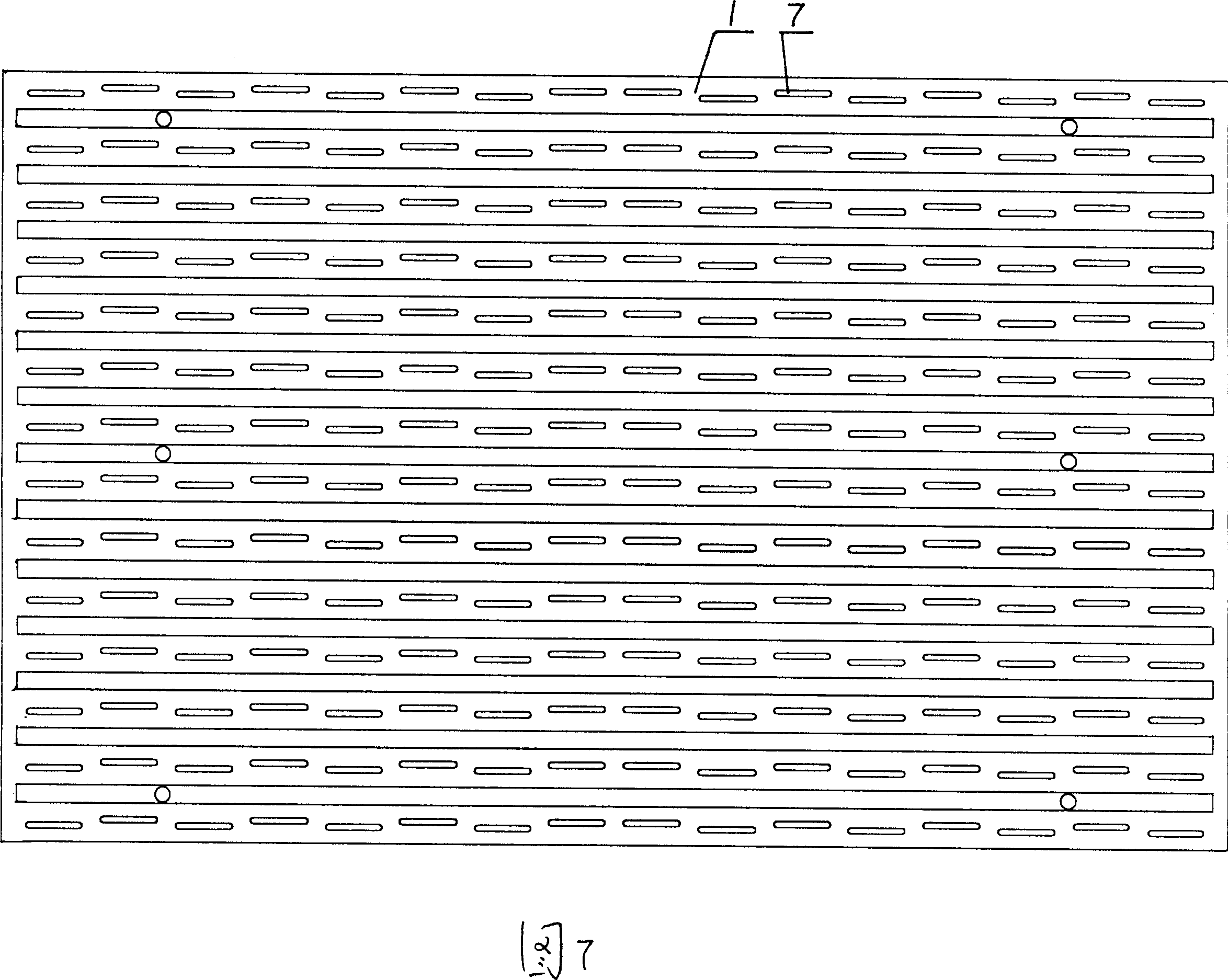
[0056] It is an embodiment of the antenna array structure of the present invention, see FIG. 7 .

[0057] This embodiment is a uniformly distributed 16-unit waveguide slot linear array. It consists of a symmetrical single ridge radiation waveguide and 16 offset longitudinal slender radiation slots arranged on it, a ridged concave symmetrical feed waveguide, a coupling slot between two kinds of ridge waveguides and a coaxial connector.

[0058] Radiation waveguide 1 is a rectangular metal radiation ridge waveguide with internal ridges and compressed width. A metal ridge is added to the center line of the bottom edge, and the metal ridge is hollow.

[0059] The feeding waveguide 2 is a concave metal feeding ridge waveguide with ridges on the bottom edge. The metal ridges are arranged outside the midline of the bottom edge of the waveguide, located directly below the radiation waveguide, and the two are complementary in structure.

[0060] The feeding ridge waveguide and the rad...


PUM


Abstract

This invention relates to a broadband single ridge waveguide slot array, resolving that the size, weight, loss, scanning angle and other aspects of existing waveguide slot array can not meet the special requirements. Its features are: the radiation waveguide has symmetric metal-single ridge on the center line of hemline and rectangular cross section, which connects with the feeding waveguide just below the bottom. The feeding waveguide has symmetric metal-single ridge on the hemline centerline. Coupling gap is set between radiation and feeding waveguide horizontally. The invention uses a single-ridge radiation waveguide to reduce the width of antenna, divides array into a number of sub-ones and feeds by power divider to improve the working bandwidth, uses ridge waveguide antenna to improve efficiency and reduce processing difficulties, uses coaxial connectors to easily realize impedance matching.

Description

technical field [0001] The invention relates to a wide-band single-ridge waveguide broadside longitudinal slot standing wave antenna. Background technique [0002] Broadband antennas are increasingly used in military and civilian applications. At the same time, in some specific applications, there are special requirements such as: volume, weight, loss and scanning angle. [0003] For example: for a wide-angle scanning planar antenna array, the distance between the antenna elements is required to be small, close to one-half of the wavelength; for a dual-polarization synthetic aperture radar antenna, the designed antenna is required to have a low profile, dual polarization, and low crossover Polarization, high isolation and other characteristics. [0004] Although the microstrip antenna is a good choice, its application range is limited due to the large loss, especially in the case of high efficiency requirements. [0005] For the waveguide slot resonant array, the bandwidt...

Claims


Application Information

Patent Timeline
Patent Type & Authority Applications(China)
IPC IPC(8): H01Q21/00H01Q21/24H01Q13/10H01P3/00
Inventor 金剑汪伟
Owner CHINA ELECTRONIC TECH GRP CORP NO 38 RES INST
Why Eureka
Try Eureka