
Variable focus lens

A lens, variable technology, applied in the field of variable focus lenses, which can solve the problems of complex lens manufacturing and so on

Inactive Publication Date: 2007-07-18
KONINKLIJKE PHILIPS ELECTRONICS NV
View PDF3 Cites 16 Cited by
  • Summary
  • Abstract
  • Description
  • Claims
  • Application Information

AI Technical Summary

Problems solved by technology

The notch is shaped such that the manufacture of such a lens is still relatively complex, and since the base of the notch is formed from the same material as the sides of the notch, if the lens is to be operative, such a material must be chosen as transparent

Method used


Image

  • Variable focus lens
  • Variable focus lens
  • Variable focus lens

Examples


Embodiment Construction

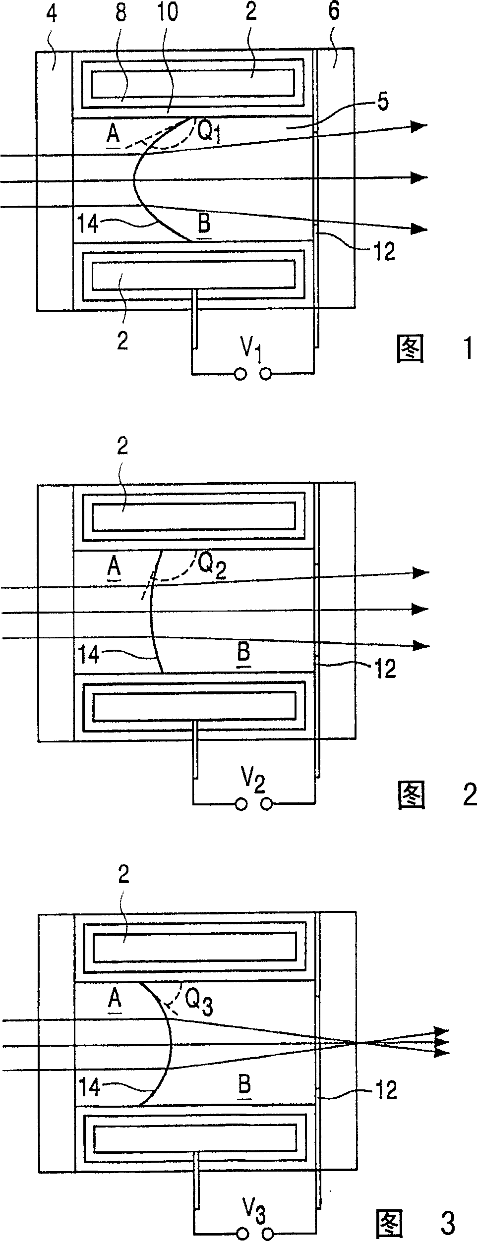
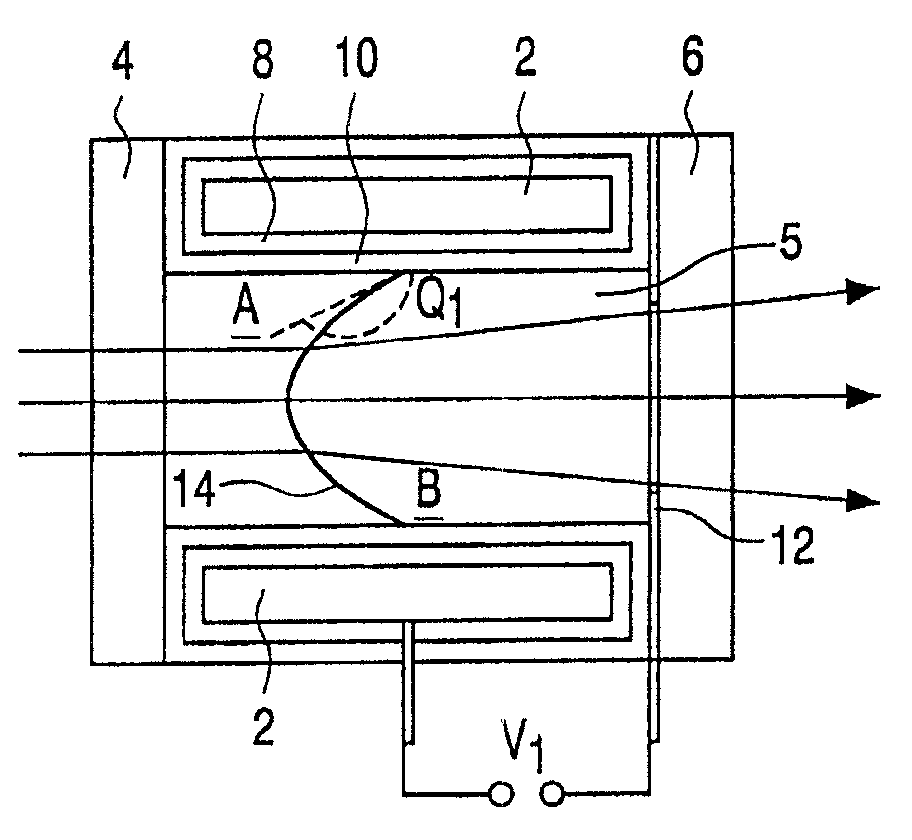
[0022] Figures 1 to 3 show a variable focus lens comprising a cylindrical first electrode 2 forming a capillary sealed by means of a transparent front element 4 and a transparent back element 6 to form a fluid container 5 containing two fluids. Electrode 2 may be a conductive coating applied to the inner wall of the tube.

[0023] In this example, the two fluids consist of two immiscible liquids in the form of an electrically insulating first fluid A, such as silicone oil or alkane, further referred to herein as "oil" ; and an electrically conductive second fluid B, such as water comprising a saline solution. The two liquids are preferably arranged to have equal densities so that the lens functions independently of orientation, ie does not rely on gravitational effects between the two liquids. This can be achieved by proper selection of the first fluid composition; for example the alkanes or silicone oils can be altered to increase their density by increasing the molecular co...


PUM


Abstract

A variable focus lens comprising a first fluid (A) and a second, non-miscible, fluid (B) in contact over a meniscus. A first electrode (2) separated from the fluid bodies by a fluid contact layer (10), and a second electrode (12) in contact with the first fluid to cause an electrowetting effect whereby the shape of the meniscus is altered. The fluid contact layer has a substantially cylindrical inner wall.

Description

technical field [0001] The present invention relates to a variable focus lens comprising a first fluid and a second fluid in contact on a meniscus; and to a method of operating such a variable focus lens. The shape of the meniscus can be controlled by voltage. Background technique [0002] A fluid is a substance that changes its shape in response to any force, tends to flow or follow the contours of its container, and includes gases, liquids, and mixtures of solids and liquids that are capable of flowing. [0003] A meniscus between a first fluid and a second fluid is said to be concave if the meniscus is empty as seen from the second fluid. If the first fluid is considered to be a lens, then according to the definition in the previous sentence, if the meniscus is concave, the lens will generally be called concave. [0004] A variable focus lens with this arrangement is described in International Patent Application WO 99 / 18456. In this arrangement, the lens comprises a co...

Claims


Application Information

Patent Timeline
IPC IPC(8): G02B3/14G02F1/01G02B7/04G02B15/00G02B26/02G11B7/00G11B7/135
CPCG11B7/13925A61B1/0019G11B7/1378G02B26/005G11B2007/0013G02B13/0075G02B3/14
Inventor B·J·菲斯特拉S·库伊佩S·斯塔林加B·H·W·亨德里克斯R·M·斯诺尔伦
Owner KONINKLIJKE PHILIPS ELECTRONICS NV
Learn More