Aerial pipe arrangement and method of aerially arranging pipes

A technology for overhead pipes and pipes, applied in the direction of pipe laying and maintenance, pipes/pipe joints/fittings, flange connections, etc., to avoid inconvenience

Inactive Publication Date: 2007-07-25
PIPE SYST JAPAN LIABILITY PARTNERSHIP
View PDF4 Cites 6 Cited by
  • Summary
  • Abstract
  • Description
  • Claims
  • Application Information

AI Technical Summary

Problems solved by technology

[0009] However, the problem with the pair of steel pipes proposed in Japanese Patent Application Laid-Open No. 63-5010 is that the steel pipes can be connected to each other, but separation of the steel pipes from each other cannot be avoided, and one of the steel pipes cannot be bent and elongated relative to the other

Method used


Image

  • Aerial pipe arrangement and method of aerially arranging pipes
  • Aerial pipe arrangement and method of aerially arranging pipes
  • Aerial pipe arrangement and method of aerially arranging pipes

Examples


no. 1 example

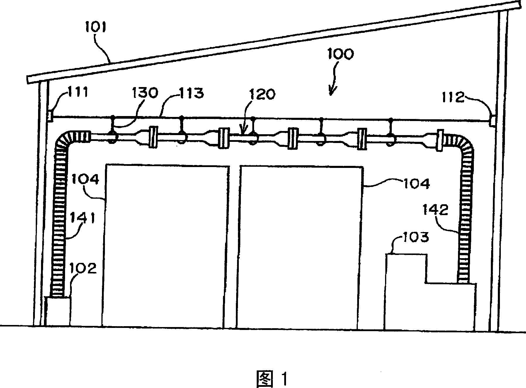
[0038] FIG. 1 illustrates an overhead duct structure 100 according to a first embodiment of the present invention.

[0039] An overhead duct structure 100 is erected in a factory 101 . An air compressor 102 is provided at one end of the factory 101 , and a machine 103 driven by compressed air is provided at the other end of the factory 101 . Assume that although the compressed air discharged from the air compressor 102 must be supplied to the machine 103, other machines 104 are provided between the air compressor 102 and the machine 103, and therefore, there is no place on the floor of the factory 101 for disposing the air compressor. 102 and machine 103 may be a space of conduits in fluid communication with each other.

[0040] The overhead pipe structure 100 according to the first embodiment of the present invention is preferably applied to a factory 101 .

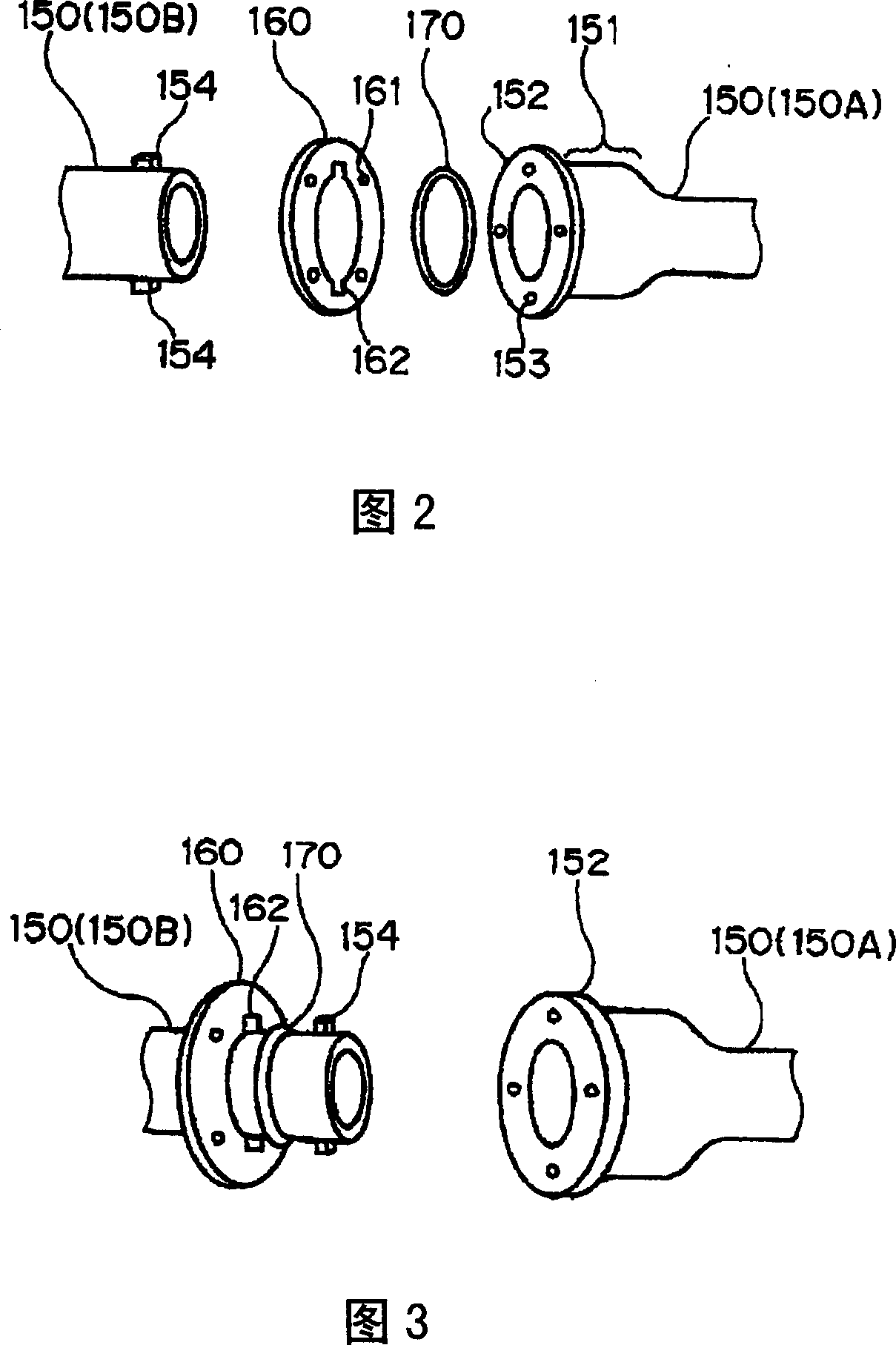
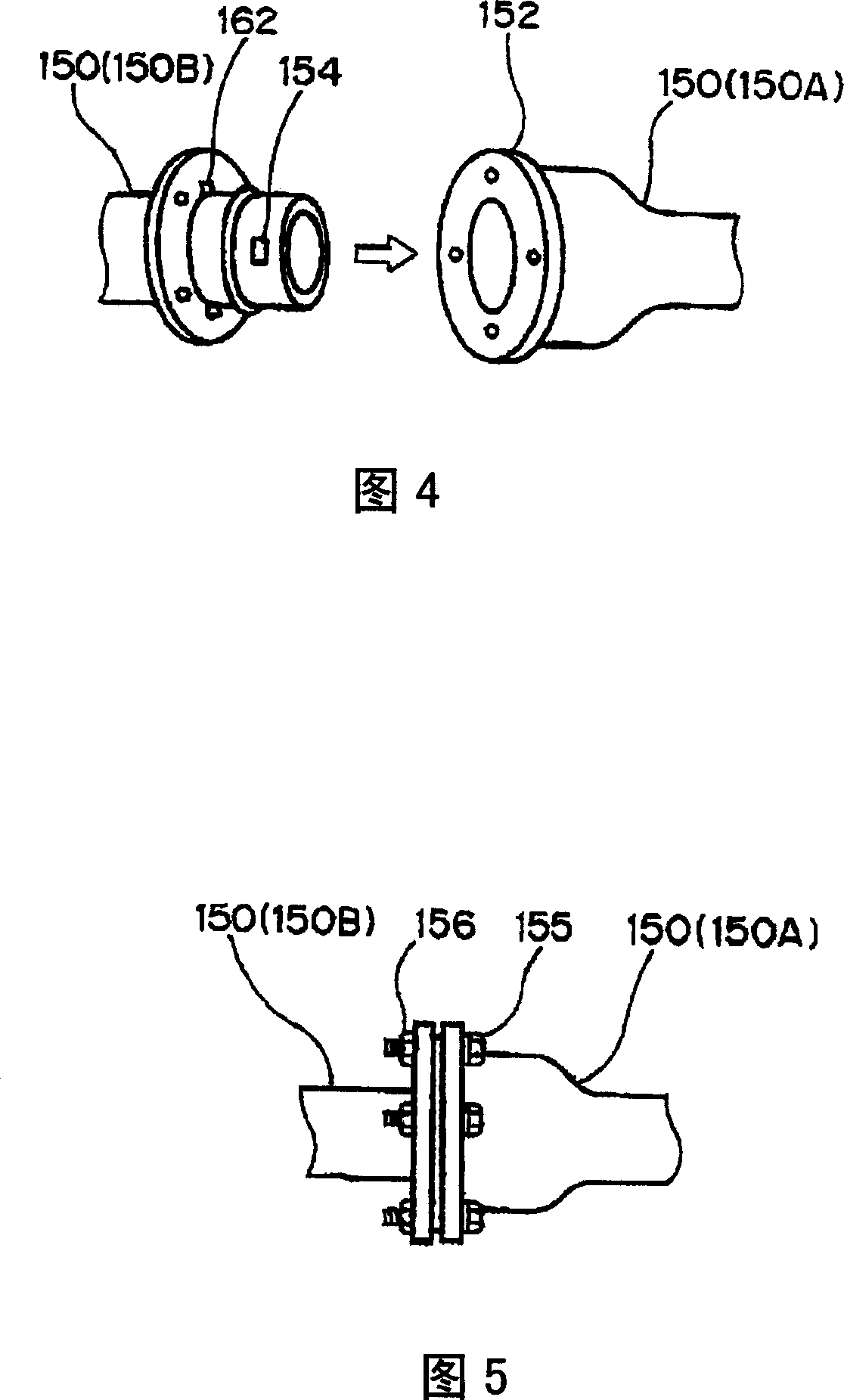
[0041] As shown in FIG. 1 , the overhead duct structure 100 according to the first embodiment includes a main cable ...

no. 2 example

[0090] FIG. 7 illustrates an overhead duct structure 200 according to a second embodiment of the present invention.

[0091] An overhead pipeline structure 200 according to a second embodiment of the present invention is erected between a first factory 201 and a second factory 202 .

[0092] The overhead duct structure 200 according to the second embodiment is structurally the same as the overhead duct structure 100 according to the first embodiment. Therefore, parts or elements corresponding to the first embodiment are provided with the same reference numerals and operate in the same manner as corresponding parts or elements in the first embodiment unless explicitly stated below.

[0093] Assume that the area 203 located between the first factory 201 and the second factory 202 is an area where it is impossible to install pipelines on the ground, such as a river, a railway, or a highway.

[0094] Even if there is an area 203 between the first factory 201 and the second factor...

no. 3 example

[0097] FIG. 8 illustrates an overhead duct structure 300 according to a third embodiment of the present invention.

[0098] As shown in FIG. 8, the overhead pipeline structure 300 according to the third embodiment of the present invention includes a first hollow supply rod 301 standing on the ground 350, a second hollow supply rod 302 standing on the ground 350, The main cable 303 tensioned between the apex of the supply rod 301 and the apex of the second supply rod 302, the fluid delivery tube 320 extending between the first and second supply rods 301 and 302, and the main cable 303 for the main cable 303 The hanger 330 from which the fluid delivery tube 320 is suspended.

[0099] In the overhead duct structure 300 according to the third embodiment, the main cable 303 is tensioned between the apex of the first supply rod 301 and the apex of the second supply rod 302 . That is, the apex of the first supply rod 301 corresponds to the first support 111 in the first embodiment, ...


PUM


Abstract

The pipe arrangement (100) for feeding fluid to a fluid-receiver (103) from a fluid-supplier (102) through a pipe, includes a wire (113) tensioned between a first support (301) and a second support (302), a hollow fluid-feeding pipe (120) extending between the first and second supports, and a hanger (130) for allowing the fluid-feeding pipe (120) to hang from the wire (113). The fluid-feeding pipe (120) is comprised of a plurality of fundamental pipes (150) capable of being connected to one another. A second fundamental pipe connected to a first fundamental pipe can extend and contract axially thereof relative to the first fundamental pipe, and can further bend obliquely relative to the first fundamental pipe.

Description

technical field [0001] The invention relates to an overhead pipeline structure and a method for arranging pipelines in an overhead manner. Background technique [0002] Water and gas pipes are often buried under roads. [0003] These pipes are traditionally buried at a depth of about 12 metres. Recently, the pipeline was buried at a depth of about 6 meters. [0004] However, it is often not possible to bury water and / or gas pipes in certain areas. For example, it is not possible to bury water and / or gas pipes under rivers, in areas where many pipes are already buried, so there is not enough space for re-burying pipes under heavy traffic, under railways, or are difficult to remove and In areas of restoration of concrete and asphalt. [0005] Japanese Patent Application Laid-Open Publication No. 63-246585 has proposed a system for arranging ducts in an overhead manner, comprising rods spaced apart from each other, cables tensioned between the rods, and suspension from the ...

Claims


Application Information

Patent Timeline
Patent Type & Authority Applications(China)
IPC IPC(8): F16L1/00F16L23/024
CPCF16L1/0246F16L1/0243F16L1/00
Inventor 关根繁之
Owner PIPE SYST JAPAN LIABILITY PARTNERSHIP
Why Eureka
Try Eureka