Vide frequency display device signal detecting method and its circuit

A technology for video display and signal detection, applied in television, electrical components, image communication, etc., can solve the problems of high cost and long judgment time, and achieve the effect of short judgment time, simple detection method and easy implementation.

Inactive Publication Date: 2007-07-25
SICHUAN CHANGHONG ELECTRIC CO LTD
View PDF0 Cites 9 Cited by
  • Summary
  • Abstract
  • Description
  • Claims
  • Application Information

AI Technical Summary

Problems solved by technology

[0005] This method takes a long time to judge and the cost is also high, especially if the chip itself does not have synchronous separation or

Method used


Image

  • Vide frequency display device signal detecting method and its circuit

Examples


Embodiment 1

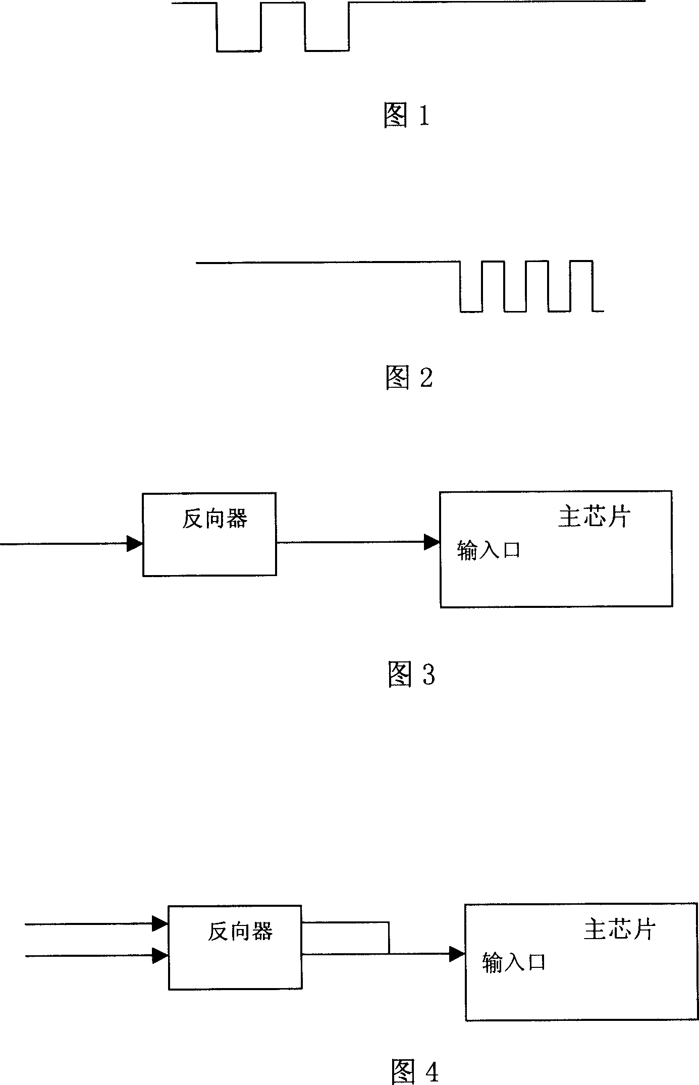
[0034] Taking the composite video signal as an example, the line and field synchronization of the composite video signal are mixed together. Its video display device signal detection circuit is shown in Figure 3, and the inverter is connected to an input terminal of the video signal state detection module. The composite video signal is reversed by the inverter to generate a detection video signal; the detection video signal is input to an input end of the video signal state detection module.

[0035] The state detection module detects the input detection video signal. As long as it finds that the level changes from high to low, it will wake up the whole machine immediately and look for the synchronization signal. If there is a synchronization signal, it will display normally; if there is no synchronization signal, the whole machine will Sleep, continue to detect synchronization; if the detected video signal level changes from low to high and it is still high after 10 consecuti...

Embodiment 2

[0037] VGA signal is different from composite video signal, its line and field synchronization are separated. The signal detection circuit of the video display device is shown in Figure 4, the output terminal of the inverter is connected to an input terminal of the video signal state detection module. An additional AND gate can also be added, the two signals output by the inverter are connected to the two input terminals of the AND gate, and the output terminal of the AND gate is connected to an input terminal of the video signal state detection module.

[0038] The state detection module detects the input signal and the detection method of the video signal is the same as that in Embodiment 1.

[0039] The above embodiment uses 74HC04 as the inverter. The high level range of this chip is 2-VCC, and the low level range is 0-0.3V, which can reliably eliminate the influence of clutter.

[0040] Take the VGA signal as an example, input the horizontal and vertical synchronous sign...


PUM


Abstract

The method comprises: reversing video signals to generate the video- detecting signal; if detecting the level having a variation from high to low, then waking up the machine; if detecting the level have a variation from low to high, and keep a high level, then letting the video display enter into standby state. The invention also provides a detection circuit thereof comprises a reverser, a video signal state detection module. The reverser is connected to an input end of the video signal detection module.

Description

technical field [0001] The invention relates to video detection technology, in particular to a technology for automatically detecting the presence or absence of signals. Background technique [0002] Usually when using a computer or TV, there will be such a situation: after the TV is turned on, there is no signal for a long time, in order to save power, protect the TV, and prevent radiation, the TV will enter the standby state; if the signal returns to normal, the TV will Still won't power on unless the user is present to control it; this control method is normal for the average user. [0003] But if it is a TV set for advertising purposes, the situation will be different. The advertising machine enters the standby state after there is no signal. When there is a signal, if the operator needs to operate on site every time before the advertising machine can be turned on, it will cause a lot of unnecessary troubles. For advertising machines and most engineering machines, shut...

Claims


Application Information

Patent Timeline
IPC IPC(8): H04N17/00
Inventor 梁敏
Owner SICHUAN CHANGHONG ELECTRIC CO LTD
Why Eureka
Try Eureka