
Rotary discharger

An unloader and rotor technology, applied in loading/unloading, rotary conveyors, conveyors, etc., to achieve the effect of extended service life, low power consumption, and improved economy

Active Publication Date: 2010-07-28
SHANGHAI CLEAR ENVIRONMENTAL PROTECTION SCI & TECH +2
View PDF6 Cites 0 Cited by
  • Summary
  • Abstract
  • Description
  • Claims
  • Application Information

AI Technical Summary

Problems solved by technology

[0003] Technical problem: In order to overcome the problems existing in the existing rotary feeder, the present invention provides a rotary unloader with good air tightness, low power consumption, no shearing of broken materials, low cost and long service life

Method used

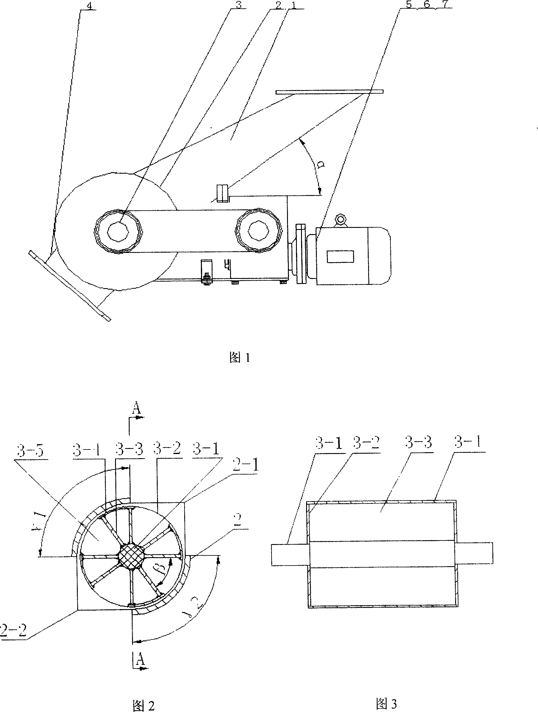

Image

  • Rotary discharger
  • Rotary discharger

Examples


Embodiment Construction

[0016] The present invention will be further described below in conjunction with the accompanying drawings and embodiments.

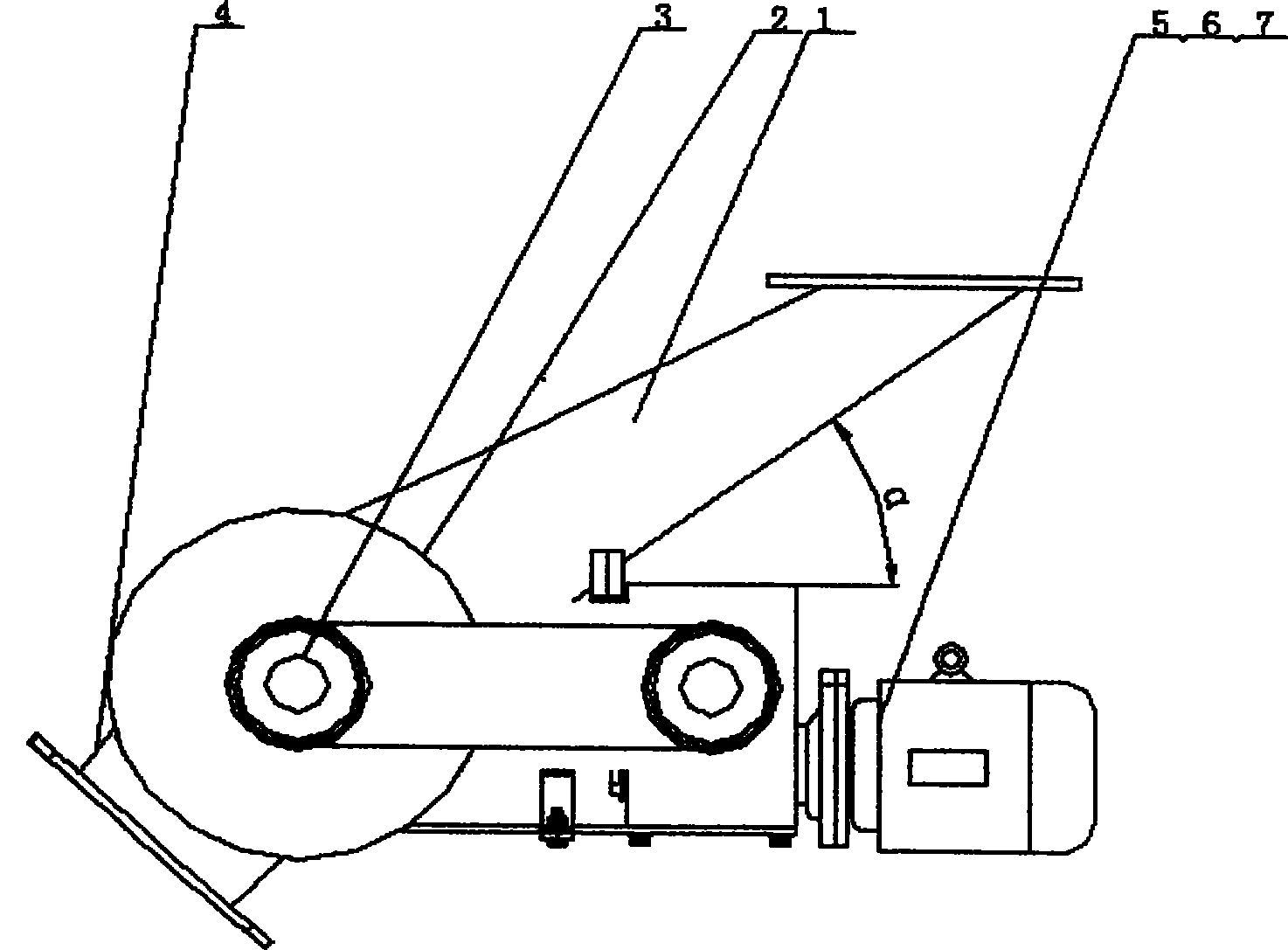
[0017] Examples of the present invention are figure 1 , The feed chute I is welded with carbon steel plate (Q235-A), and the chute angle is 45°. The unloader housing 2 and the unloader rotor 3 are made of wear-resistant 45# steel. The unloader rotor 3 has 8 blades altogether, and the included angle between the two blades is 45°. The unloader rotor has a total of 4 storage tanks, and the adjacent blades between the storage tanks are sealed with circular arc steel plates, a total of 4 places. The outer surface of the arc steel plate and the inner surface of the shell are precision machined, and the control gap is about 0.8mm. The angles of the two arcs of the housing are both 90°. The solid material in this embodiment is coke particles used for flue gas desulfurization, typical size: cylindrical coke particles with a diameter of 9mm and a length of 10...


PUM


Abstract

Rotary discharging machine relates to equipment for discharging solid materials or charging materials quantitatively. The discharging machine consists of discharging machine body and transmission components, the discharging machine body consists of discharging machine shell (2) and discharging machine rotor (3); the discharging machine rotor (3) is installed on the central axle of the dischargingmachine shell (2), the upper of the discharging machine shell (2) is equipped with charging mouth (2-1) and is connected with the charging chute (1), the lower of the discharging machine shell (2) isequipped with the discharging mouth (2-2) and is connected with the discharging chute (4); the transmission components consists of reducer (5), drive motor (6) and the drive pulley (7). The inventionis a rotary discharging machine with good air impermeability, less power consumption, not shearing broken materials, low cost and long service life .

Description

technical field [0001] The invention relates to a device for solid material unloading or quantitative feeding, and belongs to the technical field of solid material conveying equipment and unloading equipment manufacturing. Background technique [0002] A typical rotary unloader today consists mainly of a shaft or star rotor with blades or star slots sealed in a cast iron or steel housing with an inlet at the top and an outlet at the bottom. As the shaft rotates, the star chamber in the upper half of the unloader is filled with material. The shaft continues to rotate, and the material sealed in the star-shaped chamber is transferred to the lower part of the unloader, and is obliquely discharged from the discharge port by virtue of the gravity of the material. The unloader of this structure has poor air tightness during the unloading process; there is a shearing action between the blade and the casing, which will cause the material to break and increase power consumption; for...

Claims


Application Information

Patent Timeline
Patent Type & Authority Patents(China)
IPC IPC(8): B65G29/00B65G65/30
Inventor 翟尚鹏刘静
Owner SHANGHAI CLEAR ENVIRONMENTAL PROTECTION SCI & TECH
Learn More