Sampling circuit and voltage sampling method for three-level power factor calibration circuit

A power factor correction and sampling circuit technology, which is applied in the measurement of electric power, electric power measurement by current/voltage, and electric devices, etc., can solve problems such as negative interference of control circuits, eliminate negative interference, and ensure normal bus voltage detection. The effect of capacitance voltage difference detection

Active Publication Date: 2007-08-01
VERTIV CORP
View PDF0 Cites 20 Cited by
  • Summary
  • Abstract
  • Description
  • Claims
  • Application Information

AI Technical Summary

Problems solved by technology

[0007] In view of the above-mentioned defects of the prior art, the present invention will solve the problem of the control circuit in the prior art because the midpoint of the capacitance (Midpoint) is connected to the ground (GND), and the high-frequency disturbance noise disturbance at the midpoint of the capacitance will be transmitted to the ground. Problems causing negative distractions

Method used


Image

  • Sampling circuit and voltage sampling method for three-level power factor calibration circuit
  • Sampling circuit and voltage sampling method for three-level power factor calibration circuit
  • Sampling circuit and voltage sampling method for three-level power factor calibration circuit

Examples


Embodiment Construction

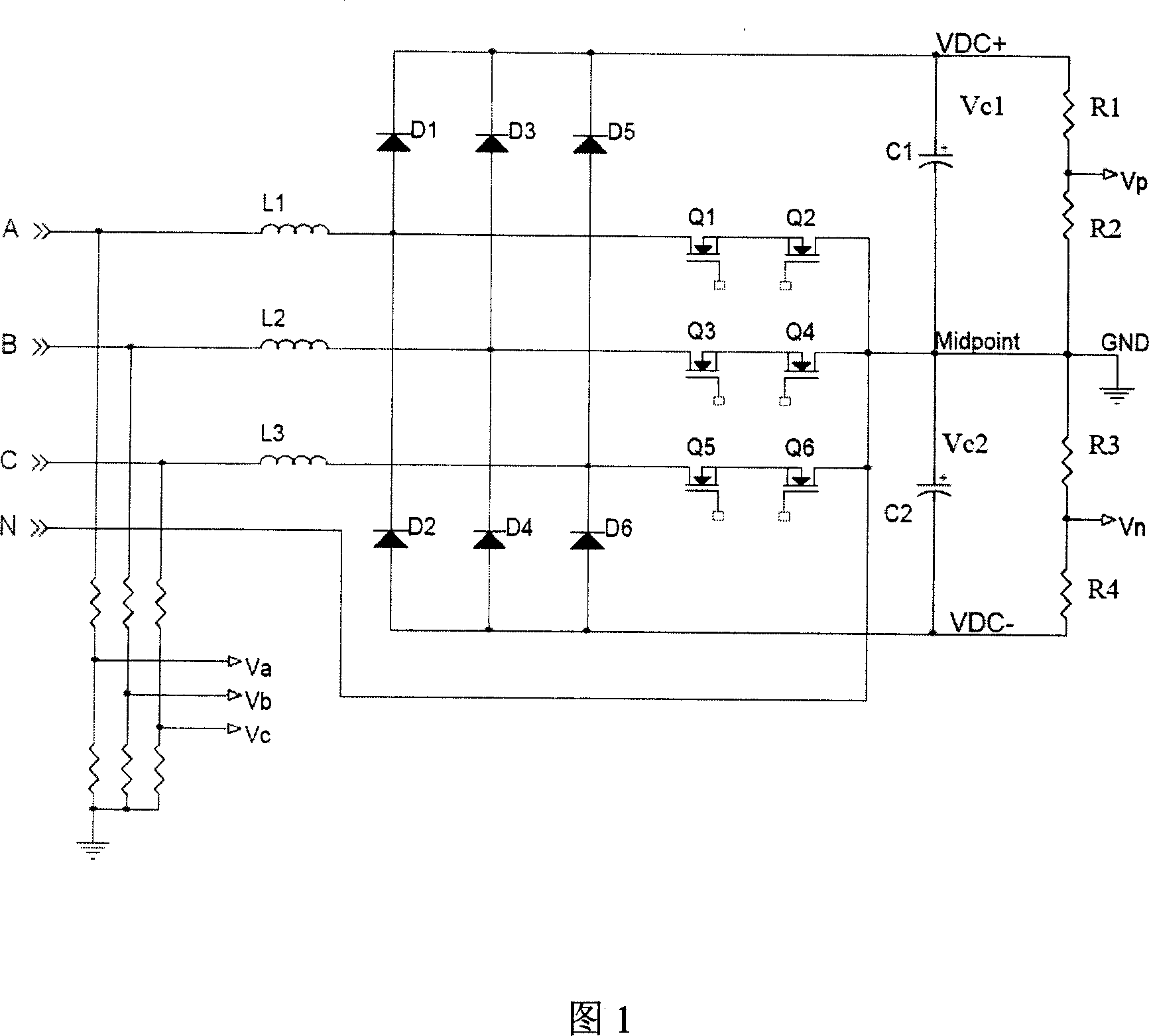
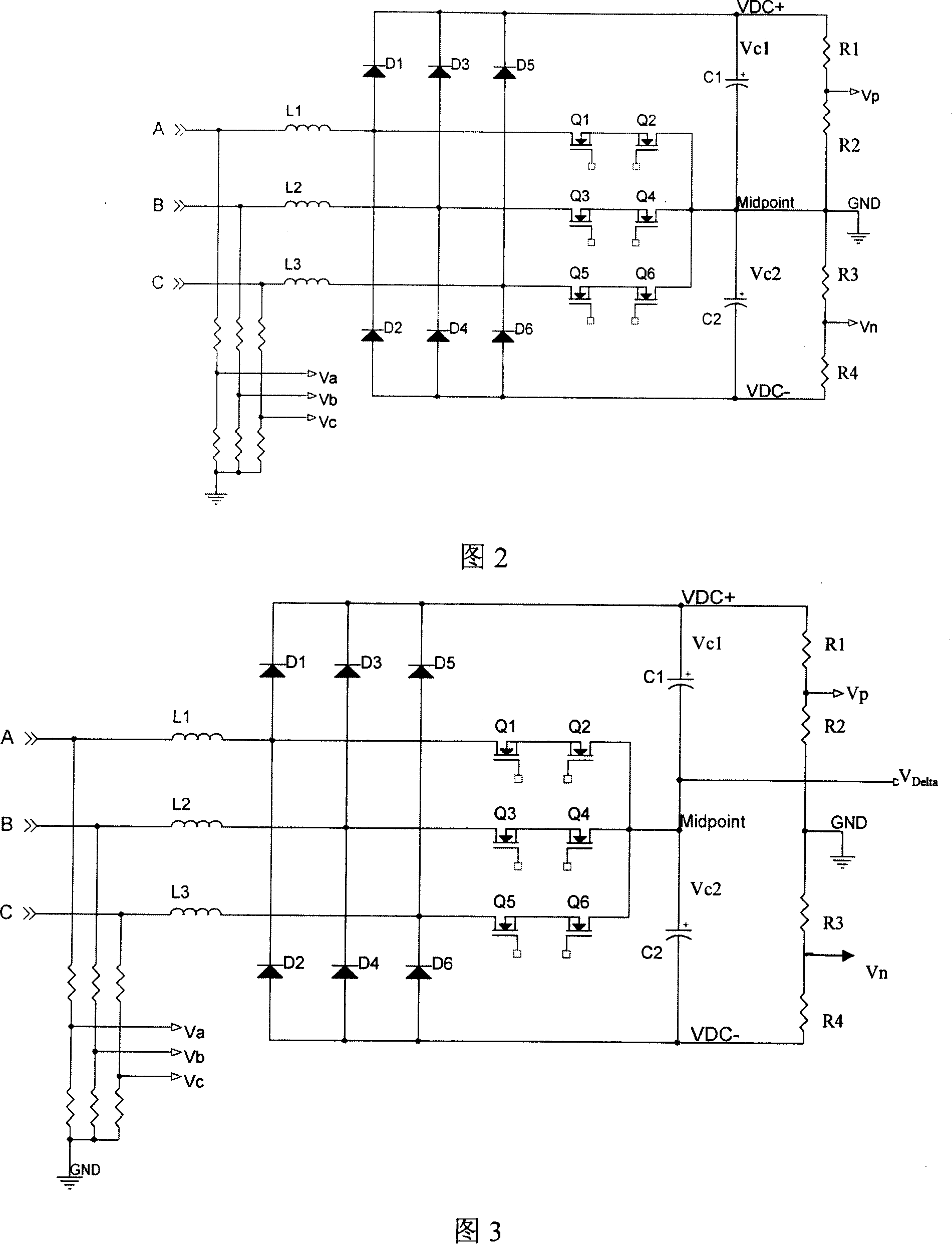
[0022] In a preferred embodiment of the present invention, voltage sampling is performed on the three-level PFC circuit in the manner shown in FIG. 3 . As can be seen from Figure 3, the difference between it and Figure 2 is that the midpoint (Midpoint) of the bus capacitors C1 and C2 are separated from the ground (GND) of the control circuit and not connected together; the rest are identical.

[0023] In Figure 3, the AC voltage sampling is also connected to the ground (GND) through the voltage divider resistors. Since the resistance values ​​of these voltage divider resistors are very large, the ground (GND) is actually suspended; at this time, the capacitor The high-frequency disturbance noise at the point will not be serially entered into the control circuit. Although there are high-frequency disturbance noises at the busbars VDC+ and VDC-, because the resistance values ​​of the voltage dividing resistors connecting them to the ground (GND) are very large, the high-frequen...


PUM


Abstract

The invention relates to a sampling circuit which is used in three level PFC circuit and voltage sampling method, aiming at solve the problem that high frequency noise of capacitance midpoint in current circuit can be transferred to the ground (GND) which is connected with it affect the control circuit, in the sampling circuit of the invention, the midpoint of the resistance R2, R3 is connected with ground all the way, but the midpoint of the generatrix capacitance C1,C2 and the ground are cut structure, so the high frequency noise of capacitance midpoint can not be transferred to the control ground. Aiming at obtain the generatrix voltage and the voltage difference between the generatrix capacitance C1,C2, the invention regards the ground as reference point, the midpoint of resistance R1,R2 is sampled to obtain the Vp, the midpoint of resistance R3,R4 is sampled to obtain the Vn, the midpoint of capacitance C1,C2 is sampled to obtain the VDelta, based on the three voltage value, the relative generatrix voltage and voltage difference between the generatrix capacitance C1,C2 can be obtained.

Description

technical field [0001] The invention relates to a voltage sampling technology for a three-level PFC (power factor correction) circuit, more specifically, a sampling circuit for a three-level PFC circuit and a method for sampling the voltage of a bus capacitor. Background technique [0002] The three-level PFC circuit of the three-phase four-wire system is shown in Figure 1. Among them, A, B, C are three-phase AC input, N line is neutral line input, L1, L2, L3 are inductors, Q1~Q6 are switching tubes with anti-parallel diodes, D1~D6 are freewheeling diodes, C1, C2 is the equivalent capacitance on the bus. The three-phase AC input passes through the switching tubes Q1~Q6, the freewheeling diodes D1~D6, and after the conversion process with the capacitors C1 and C2, the output is the corresponding DC voltage VDC+ and VDC-. [0003] Since the midpoint of the output capacitor (Midpoint) is connected with the N line, it is a very stable point, so the ground of the control circui...

Claims


Application Information

Patent Timeline
Patent Type & Authority Applications(China)
IPC IPC(8): H02J3/18G05F1/70G01R21/00G01R21/06
CPCY02E40/30Y02P80/10
Inventor 黄伯宁钟宇明
Owner VERTIV CORP
Why Eureka
Try Eureka