Excavating tool and steel pipe forepoling method

A tool and front-end technology, applied in the field of advanced support of steel pipes, can solve the problems of reduced discharge efficiency, difficult opening and discharge of check valves, etc., and achieve the effect of preventing the reduction of discharge performance and preventing loosening

Inactive Publication Date: 2007-08-01
MITSUBISHI MATERIALS CORP
View PDF10 Cites 2 Cited by
  • Summary
  • Abstract
  • Description
  • Claims
  • Application Information

AI Technical Summary

Problems solved by technology

In order to avoid such a situation, it is necessary not to use the excavation water or to reduce the amount of excavation water used, and there is a problem that excavation debris accumulates in the gap between the steel pipe and the inner rod, which reduces the discharge performance of the excavation debris
In this way, it will be difficult to discharge the excavated debris, not only the speed of digging will become very slow, and the digging operation may not be continued.
In addition, even when only air is used to discharge excavated debris instead of boring water, sufficient discharge performance cannot be obtained.
[0008] In addition, in the case of a structure in which the check valve is pushed open by the internal pressure of the injection agent or the check valve is separated to open during the injection operation as in Patent Document 1, the outer side of the steel pipe is the hole wall of the excavated hole, It is possible that the check valve cannot be opened due to being blocked by the hole wall
In particular, due to the state of excavation, sand and soil may accumulate between the steel pipe and the excavation hole, and the pressure of the sand and soil may become an obstacle to the opening.
In this way, since the check valve becomes difficult to open, it is difficult to discharge the injection agent from the filter hole, and the effect of strengthening the mountain body cannot be obtained sufficiently.
[0009] In addition, in the above-mentioned steel pipe advance support method, when excavating a highly viscous and poorly fluid formation such as clay, excavation debris passing through the gap between the steel pipe 5 and the inner rod is accumulated in the gap and discharged. The problem of reduced efficiency
Moreover, it is possible that the excavation debris accumulated in this way is piled up one by one, making it difficult to discharge the excavation debris, thereby making it impossible to continue the digging operation.
In addition, in order to suppress the further softening of the mountain due to the excavation water when the ground is soft, or to suppress the impact on the buildings on the surface when the cover soil with the surface is shallow, it is necessary to reduce the amount of excavation water. amount of use, or air must be used instead of borehole water, in which case especially the accumulation of excavation debris becomes a problem

Method used


Image

  • Excavating tool and steel pipe forepoling method
  • Excavating tool and steel pipe forepoling method
  • Excavating tool and steel pipe forepoling method

Examples


Embodiment approach 1

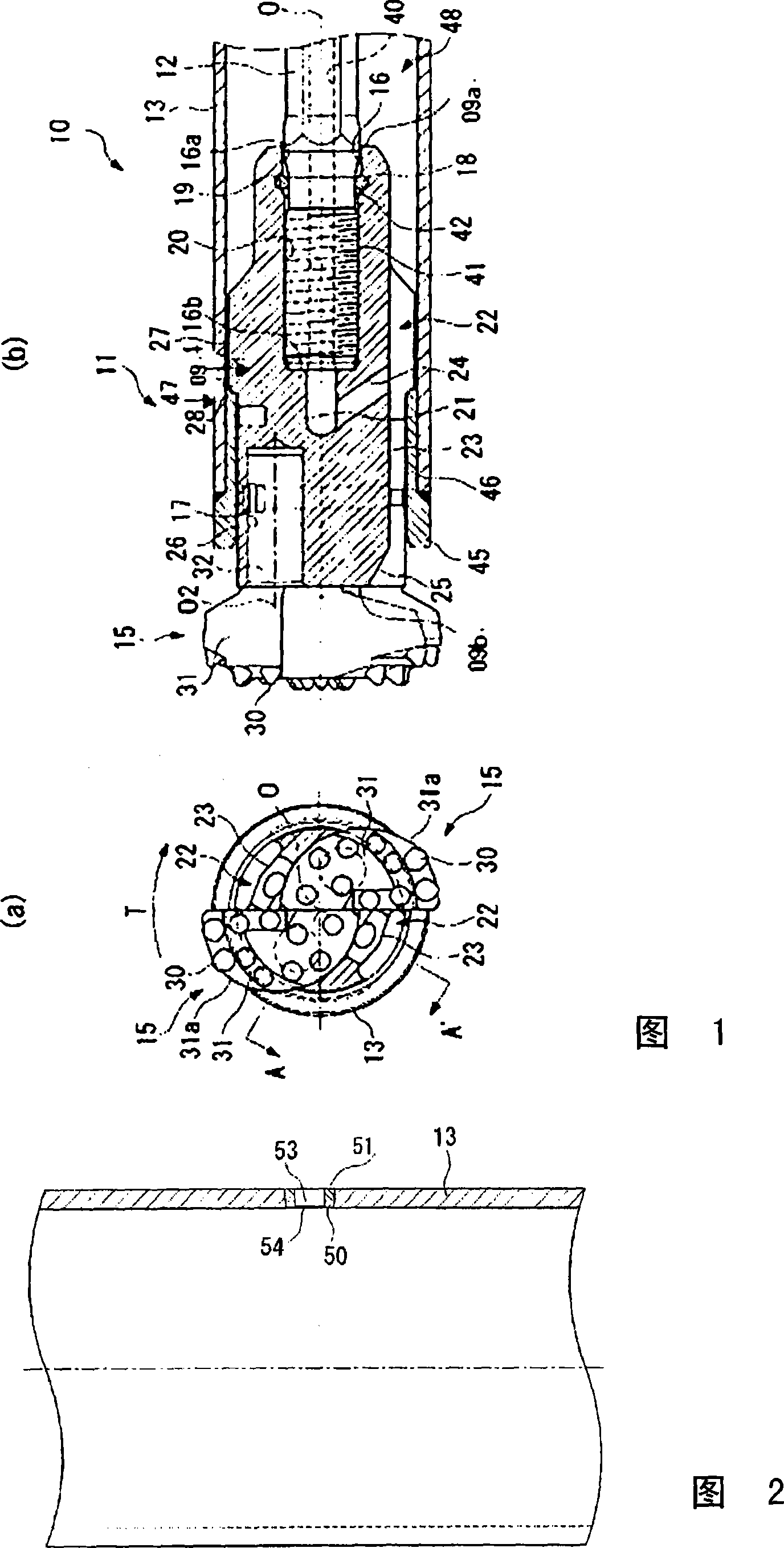
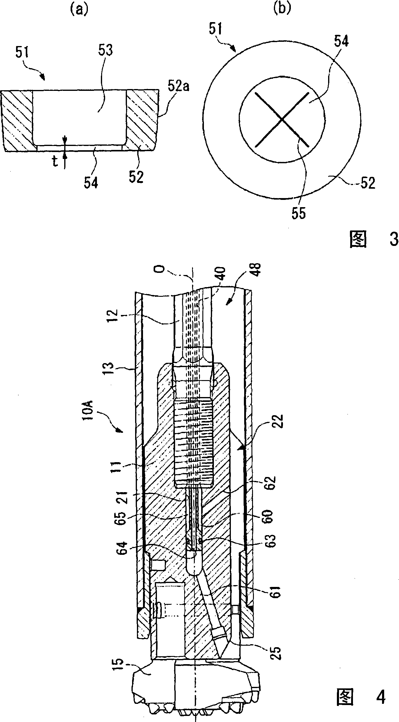
[0067] Hereinafter, Embodiment 1 of the present invention will be described with reference to FIGS. 1 to 4 .

[0068] Fig. 1 shows the front end portion of an excavating tool 10 as a first embodiment of the present invention, Fig. 1(a) is a view of the excavating tool 10 viewed from the front end side of the axis 0, and Fig. 1(b) is a partial cross section of the excavating tool 10 The side view, the cross section of Fig. 1(b) is the cross section of A-O-A' shown in Fig. 1(a). In addition, the arrow direction shown in FIG. 1( a ) is the rotation direction T during excavation, and the left side of FIG. In this embodiment, the excavating tool 10 is provided with a tool body 11 positioned at the foremost end to excavate a mountain body, a digging rod 12 that attaches the tool body 11 to the front end and transmits a driving force, and a cylindrical shaft into which the digging rod 12 can be inserted. Steel pipe 13 and constitute.

[0069] The tool main body 11 includes a device...

Embodiment approach 2

[0086] Embodiment 2 of the present invention will be described with reference to FIGS. 6 to 11 .

[0087] FIG. 6 shows the overall structure of the digging tool 10 according to the first embodiment of the present invention, and FIG. 7 shows the front end portion of the digging tool 10 . In addition, FIG. 7(a) is a view of the excavating tool 10 viewed from the front end side of the axis O, and the arrow direction indicates the rotation direction T during excavation. FIG. 7(b) is a partial cross-sectional side view of the excavating tool 10, and the left side is On the front end side of the excavating tool 10 , the front end direction is defined as the front of the excavation progress direction. The excavating tool 10 is provided with an auger bit (tool body) 11 positioned at the front end to excavate a mountain body, a digging rod 12 with the auger bit 11 mounted on the front end to transmit driving force, and a cylindrical steel pipe ( housing) 13 and an intermediate sleeve ...


PUM


Abstract

An excavating tool capable preventing the natural ground from being loosened by excavated water and smoothly discharging excavated chips and a steel pipe forepoling method capable of securely providing earth reinforcing effects by using the excavating tool. The excavating tool (10) comprises a boring rod (12) rotatingly drivable around an axis (0), a tool body (11) fitted to the front of the boring rod (12) in the forward excavating direction, and a cylindrical steel pipe (13) having a specified clearance relative to the boring rod (12) with the boring rod (12) inserted therein. The excavating tool is characterized in that a flow passage (21) for supplying drilling water to the axial forward direction is formed in the tool body (11), and a fluid supply port (24) communicating with the flow passage (21) and jetting the drilling water is formed only at a position on the tool body opening to the inside of the steel pipe (13) toward the rear of the tool body (11) in the forward excavating direction.

Description

technical field [0001] The present invention relates to an excavating tool configured by inserting a digging rod with a tool body attached to its tip into a steel pipe (housing), and used for digging a steel pipe while forming an excavation hole in a mountain body with the tool body, and A steel pipe advance support method in which an injectant is injected after a hole-digging operation using the excavating tool to reinforce the mountain body. [0002] In addition, the present invention relates to an excavating tool in which a digging rod with a tool main body attached to its front end is inserted into a housing, the digging rod is inserted into the housing while forming an excavation hole on a mountain body with the tool main body, and the digging rod is sequentially inserted into the housing. It is used in the digging operation where the excavation hole of a predetermined depth is formed by connecting with the casing. Background technique [0003] Generally, in tunnel exc...

Claims


Application Information

Patent Timeline
Patent Type & Authority Applications(China)
IPC IPC(8): E21B10/60E21B10/44E21B17/18E21B17/22
CPCE21B10/44E21B21/12E21B10/60E21B17/22
Inventor 林猛久田仁也中村和由
Owner MITSUBISHI MATERIALS CORP
Why Eureka
Try Eureka