Device for purifying exhaust gases of a motor vehicle and method for the production thereof

An exhaust gas purification device and exhaust gas technology, which can be applied to exhaust devices, mufflers, machines/engines, etc., can solve problems such as uneven quality of welds, and achieve the effect of accurate adjustment.

Inactive Publication Date: 2007-08-01
ARVINMERITOR EMISSIONS TECH GMBH
View PDF0 Cites 11 Cited by
  • Summary
  • Abstract
  • Description
  • Claims
  • Application Information

AI Technical Summary

Problems solved by technology

Otherwise, the radial part will protrude more or less around the perimeter compared to the tube, which will result in uneven quality of the weld along the perimeter

Method used


Image

  • Device for purifying exhaust gases of a motor vehicle and method for the production thereof
  • Device for purifying exhaust gases of a motor vehicle and method for the production thereof
  • Device for purifying exhaust gases of a motor vehicle and method for the production thereof

Examples


Embodiment Construction

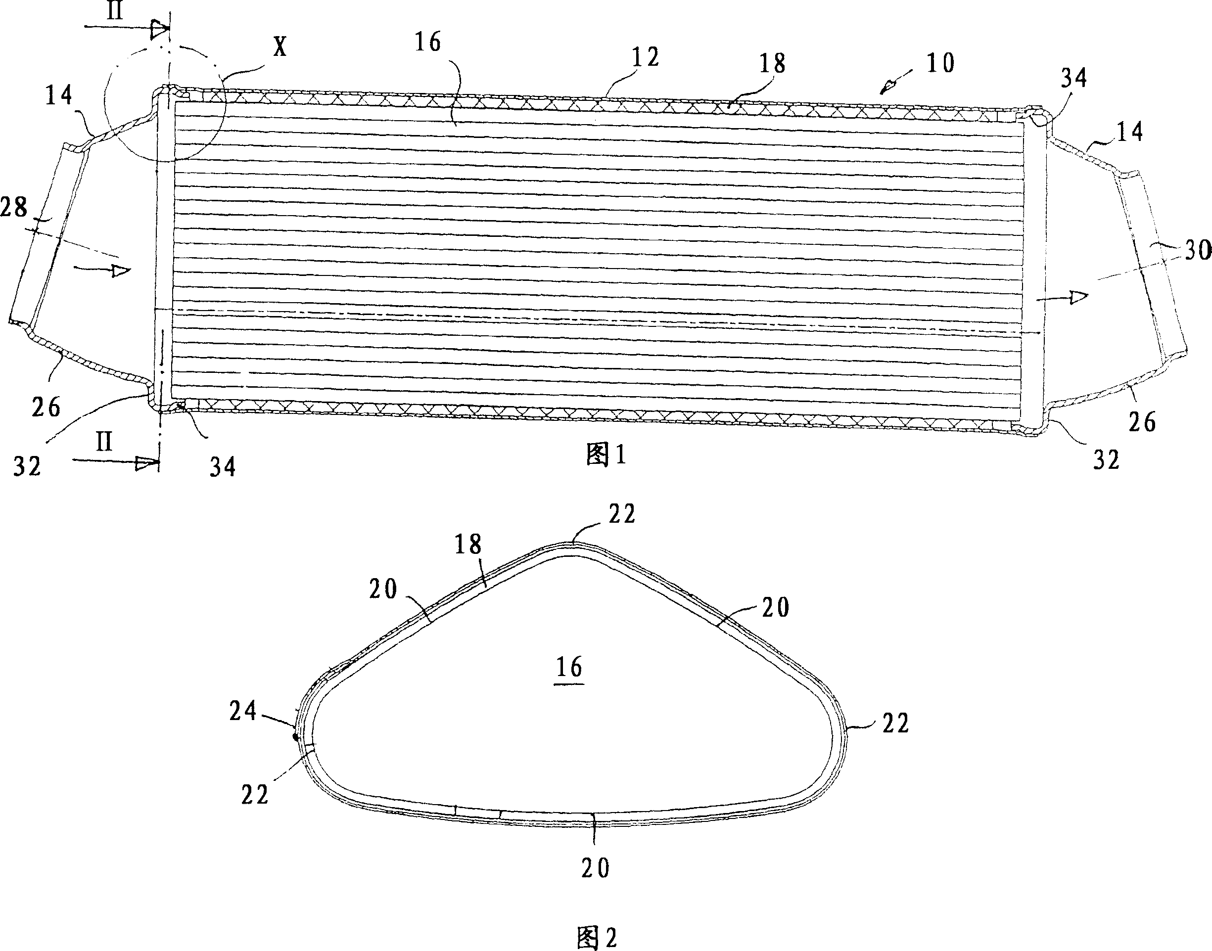
[0035] Figure 1 shows a vehicle exhaust purification device installed in the exhaust system. The device has a three-part housing 10 comprising a tube 12 longitudinally welded from sheet metal forming a surrounding sheath, and an end wall 14 mounted on the open end face of the tube 12 . A filter body 16 through which the exhaust gas flows is inserted into the housing 10 in the form of an integral diesel particulate filter or a catalytic converter (see arrow). The filter body 16 is surrounded by an insulating or intumescent pad 18 which supports the filter body 16 in the housing 10 with a non-positive fit. The pads 18 also function to compensate for tolerances and limit the deflecting forces exerted by the housing 10 on the filter body 16 .

[0036] Both the filter body 16 and the tube 12 have a geometry different from that of a circular ring and are delimited by three sections 20 that are planar or not curved at all and three relatively very curved sections 22 of the connectin...


PUM


Abstract

The invention relates to a device for purifying exhaust gases of a motor vehicle comprises a multi-part external housing (10) provided with a tube (12) and front funnel-shaped walls (14). Said tube (12) and the front walls (14) are fitted into each other and soldered or welded with each other.

Description

technical field [0001] The invention relates to a vehicle exhaust purification device comprising a multi-part housing comprising a tube formed by a continuous jacket part and an end wall arranged at the axial end of the tube and having an outlet and an inlet, and a filter body housed in the housing, The exhaust gas passes through the filter body and is purified by the filter body. Background technique [0002] Vehicle exhaust gas purification systems of this type are, for example, catalytic converters or particulate filters. The filter body is formed, for example, from extruded monolithic monoliths bonded to each other, in particular SiC material. The end wall of the housing has a funnel portion that flares towards the tube and is adjacent to the radial annular portion. An insulating or intumescent mat is wrapped around the filter body inside the unit, and a sheet metal sheath is then wrapped around the mat. The sheet metal sheath is turned into a tube by longitudinal wel...

Claims


Application Information

Patent Timeline
Patent Type & Authority Applications(China)
IPC IPC(8): F01N7/18F01N3/28F01N13/18
CPCF01N3/2853F01N13/185F01N13/1894Y02A50/20F01N3/08F01N3/021
Inventor 埃里希·福斯特彼得·克罗纳奥托·施泰因豪泽
Owner ARVINMERITOR EMISSIONS TECH GMBH
Why Eureka
Try Eureka