Blade for a single-blade vacuum pump

A vacuum pump and single vane technology, which is applied in the direction of pumps, pump components, rotary piston pumps, etc., can solve the problems of high power consumption of vacuum pumps, and achieve the effects of low power consumption, reduced weight and simple assembly

Active Publication Date: 2007-08-01
JOMA POLYTEC
View PDF0 Cites 1 Cited by
  • Summary
  • Abstract
  • Description
  • Claims
  • Application Information

AI Technical Summary

Problems solved by technology

Due to the high weight of the rotor, which has a high moment of inertia, the power consumption of the vacuum pump is annoyingly high

Method used


Image

  • Blade for a single-blade vacuum pump
  • Blade for a single-blade vacuum pump
  • Blade for a single-blade vacuum pump

Examples


Embodiment Construction

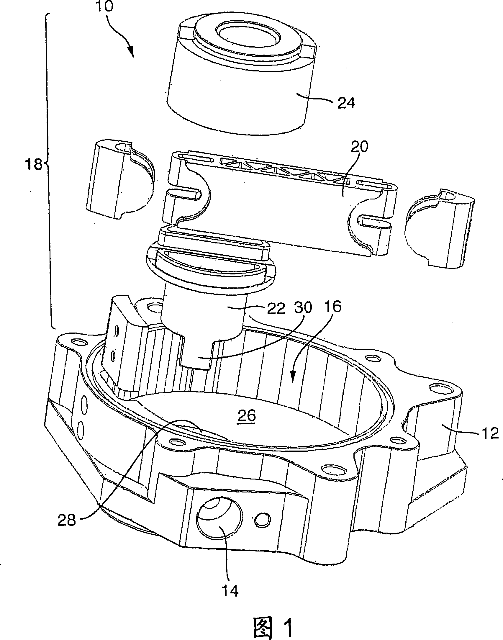
[0019] The vacuum pump as a whole is designated by the reference numeral 10 in FIG. 1 , the housing 12 being shown without a housing cover. The housing 12 has a suction connection 14 which opens into an interior 16 . In this interior space 16 is located a rotor, indicated as a whole by 18 , in which rotor blades 20 are mounted displaceably perpendicular to the axis of rotation 21 . The rotor 18 is composed of two parts and has a rotor shaft 22 and a rotor housing 24 . The rotor shaft 22 penetrates the joint housing 12, in particular through the drive opening 28 through the bottom 26 of the joint interior chamber 18, and a rectangular section 30 protrudes from the housing 12 at the rear, by means of which (by means of a drive not shown) the The rotor shaft turns. The drive opening 28 is provided with a suitable sealant so that lubricant cannot escape from the interior 16 and air and / or dirt cannot enter the interior 16 .

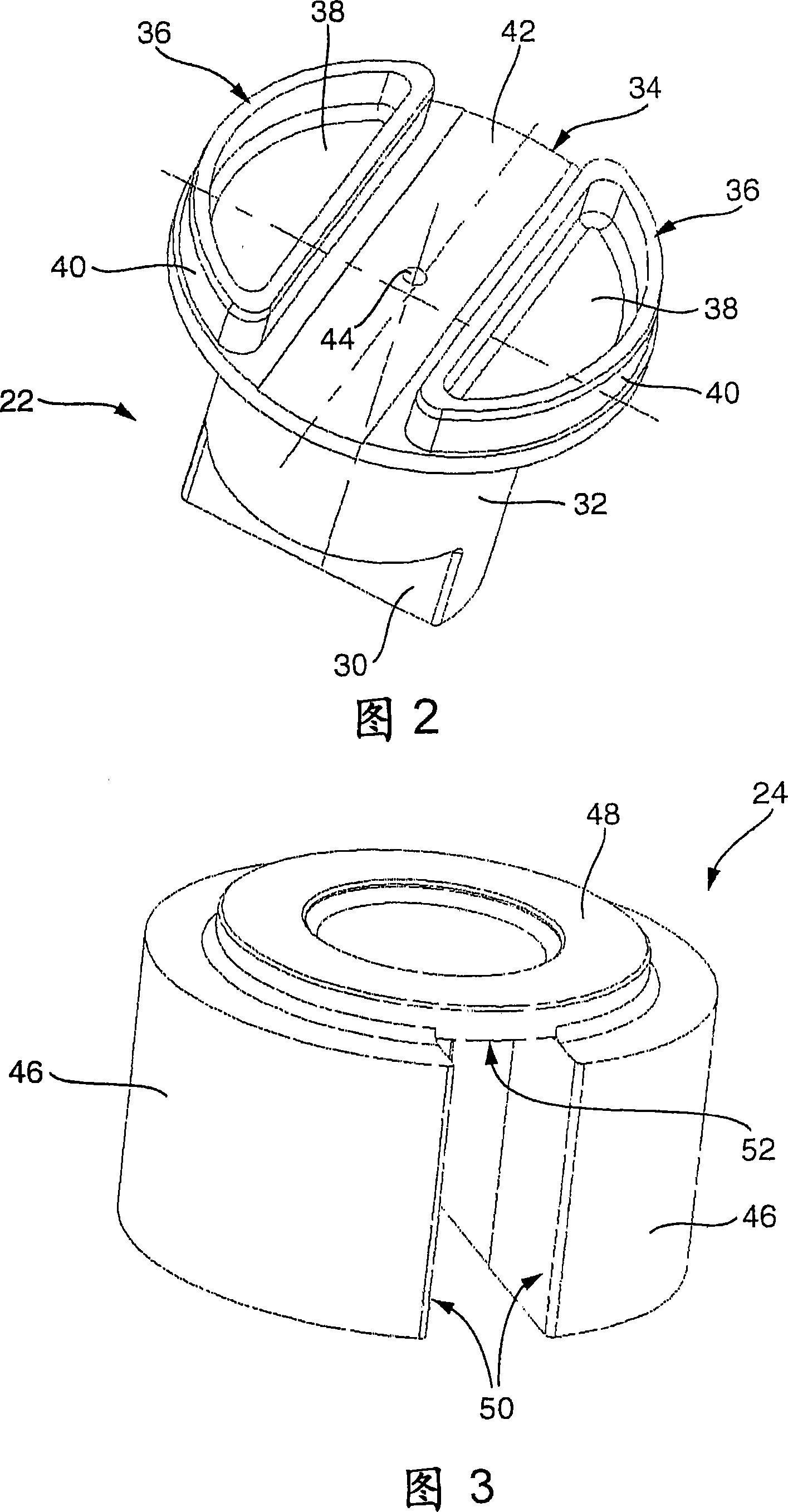
[0020] As can be seen from FIG. 2 , segment 30 exten...


PUM


Abstract

The invention relates to a single-blade vacuum pump comprising a pot-shaped housing (12), a rotor (18) mounted in the housing in such a way that it can be eccentrically rotated, a blade (20) mounted in the rotor in such a way that it can be orthogonally displaced in relation to the rotational axis, and a housing cover which is used to close the working regions separated by the blade (20). According to the invention, the rotor (18) at least partially consists of sintered metal.

Description

technical field [0001] The invention relates to a single vane vacuum pump having a cup-shaped housing, a rotor eccentrically rotatably mounted in the housing, vanes movably mounted in the rotor perpendicular to the axis of rotation, and means for enclosing the working spaces separated by the vanes Housing cover. Background technique [0002] Vacuum pumps having such a structure are known. It usually has a metal housing in which the rotor is rotatably mounted and in which the working space is formed. For example, the motor of a car drives the rotor. It is also known that the rotor is made of metal and in particular of cemented carbide. Due to the high weight of the rotor, which has a high moment of inertia, the power consumption of the vacuum pump is annoyingly high. Contents of the invention [0003] It is therefore the object of the present invention to provide a vacuum pump, in particular a single-vane vacuum pump with a low power consumption. [0004] According to ...

Claims


Application Information

Patent Timeline
Patent Type & Authority Applications(China)
IPC IPC(8): F04C18/344
CPCF04C2220/10F01C21/0809F04C18/3441F04C2240/20F04C2230/22F04C18/344
Inventor 维利·施奈德马丁·托马弗里德黑尔姆·普菲策尔
Owner JOMA POLYTEC
Why Eureka
Try Eureka