Peeling member and peeling device

一种构件、剥离片的技术,应用在仪器、应用电荷图形的电记录工艺的设备、光学等方向,能够解决无法得到图像、磨损、纸张易受到污染等问题,达到剥离性优异的效果

Inactive Publication Date: 2018-08-03
NTN CORP
View PDF7 Cites 2 Cited by
  • Summary
  • Abstract
  • Description
  • Claims
  • Application Information

AI Technical Summary

Problems solved by technology

Since the separation claw is partially in contact with the roller, it is inevitable that a part of the roller is worn and a good image cannot be obtained
In addition, there are cases where the developer transferred onto the paper is easily scraped off because the separation claw is also partially in contact with the paper, and the scraped developer also adheres to the separation claw so that the paper is easily contaminated

Method used


Image

  • Peeling member and peeling device
  • Peeling member and peeling device
  • Peeling member and peeling device

Examples


Embodiment 1

[0060] After a stainless steel (SUS304CSP) coil with a thickness of 1.5 mm was processed into a predetermined size using a progressive stamping die, the tip portion was tapered by machining to manufacture a peeling member. based on Figure 8 The manufacturing process will be described. Figure 8 It is a schematic diagram of the manufacturing process. (A) to (F) are schematic processing procedures. First, the outer dimensions of the peeling sheet are punched out of the steel plate 20 shown in (A) with a punching die, and then, the concave portion 3c is formed by drawing shown in (B). Next, in (C), the bolt hole 3d for bolt fixing is punched out with a press die, and in (D), the drawn portion is cut into a predetermined size. Then, in (E), the peeling sheet 10' before forming a cone is punched out from the steel plate 20. Finally, in (F), the side opposite to the drawing portion opposite to the paper feed is cut into a tapered shape by machining, and then ground to obtain a ...

Embodiment 2

[0064] A stainless steel (SUS304CSP) coil with a thickness of 1.5 mm was processed to a predetermined size using a progressive die in the same manner as in Example 1, and then the thickness of the tip portion was processed to 0.3 mm by machining to manufacture a release member. The punching process using the stamping die is Figure 8 The processing sequence of (A) to (E), but after the peeling sheet 10' is punched out from the steel plate 20 after being processed by a stamping die, the tapered front end is cut in the longitudinal direction by stamping to improve the accuracy of straightness , the above-mentioned tapered tip is at Figure 8 In (F), the peeling sheet 10 having the peeling portion 2 and the support portion 3 is obtained by grinding the side opposite to the drawing portion opposite to the paper feeding into a tapered shape by machining. The thickness of the leading end portion of the release sheet 10 was 0.3 mm, and the width of the release portion of the release...


PUM


Abstract

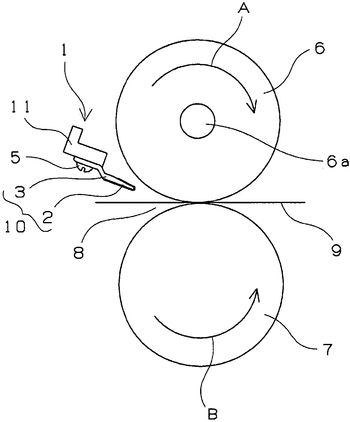
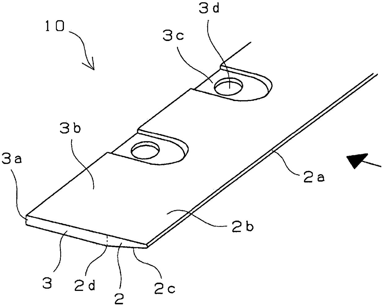
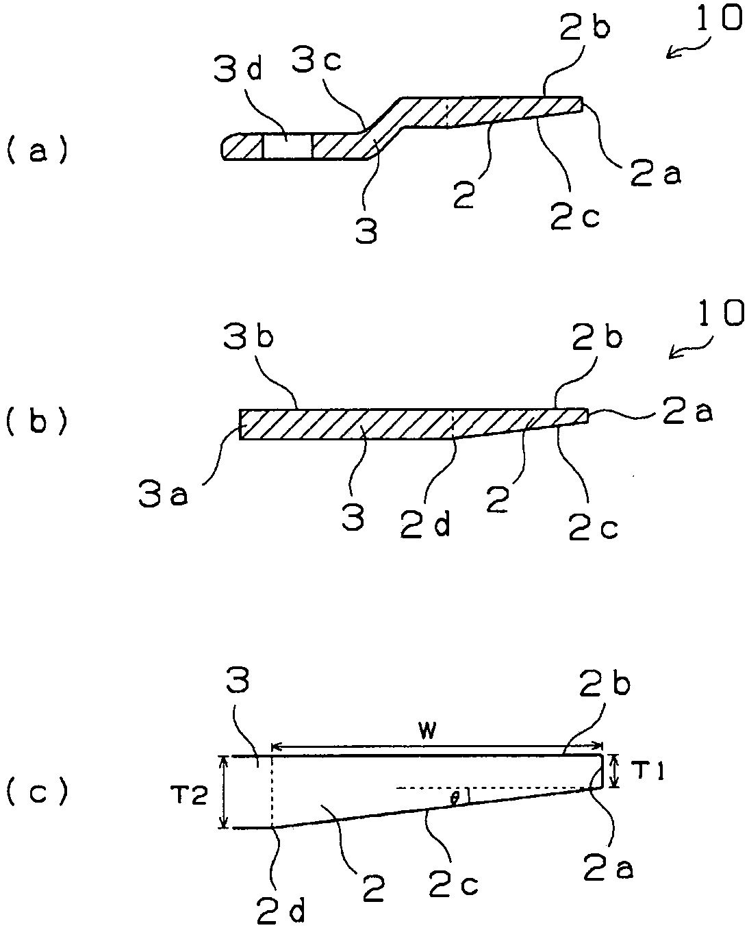
Provided are a peeling member that can suppress the phenomenon of peeling sheet creasing, can have sufficient linear contact with a roller, can prevent deformation by jamming of paper, and can exhibitsuperior paper peeling performance, and a peeling device provided with this peeling member. The peeling member, which has a peeling sheet (10) for peeling paper from an electrophotographic device fuser roller (6), is formed from one metal plate and has a peeling part (2) constituting a tip part and a support part (3) that is thicker than the peeling part (2). The peeling part (2) is provided on one long side of the metal plate, a paper passing surface (2b) thereof is a flat surface continuous with the surface of the support part (3), and the side opposite from the paper passing surface is aninclined surface (2c) inclined with respect to the paper passing surface (2b) such that the thickness of the peeling part (2) increases from the very tip (2a) of the peeling part (2) toward a boundarypart (2d) with the support part (3). The inclined surface (2c) is the surface disposed on the fuser roller (6) side, and distance (D1) between the very tip (2a) and the roller and distance (D2 from the boundary part (2d) and the roller satisfy D1<=D2<=5*D1.

Description

technical field [0001] The present invention relates to a peeling member for peeling paper from various rollers provided in electrophotographic devices such as copiers and laser beam printers, and more particularly to a peeling member for fixing members such as fixing rollers. Moreover, it is related with the peeling apparatus provided with this peeling member. Background technique [0002] In electrophotographic devices such as copiers and laser beam printers, various rollers are provided for fixing the electrostatic latent image formed on the photosensitive drum to paper after developing it with a developer such as toner paint. The developing section includes an oil application roller and the like in addition to the photosensitive drum and the dry electrophotographic device, and the fixing section includes a fixing roller, a pressure roller, and the like. Conventionally, separation claws have been provided on photosensitive drums, fixing rollers, pressure rollers, etc. in...

Claims


Application Information

Patent Timeline
Patent Type & Authority Applications(China)
IPC IPC(8): G03G15/20G03G15/14
CPCG03G15/2028G03G15/14G03G2215/2093G03G15/6532G03G15/2053G03G15/16G03G15/06G03G15/02
Inventor 广濑和夫
Owner NTN CORP
Why Eureka
Try Eureka