Stuffing separating equipment
A filling divider and pusher technology, which is applied in baking, dough handling, food science and other directions, can solve the problems of difficulty in filling the same specifications, high degree of specialization, and low production efficiency, saving working time, The effect of reducing labor intensity and improving production efficiency
- Summary
- Abstract
- Description
- Claims
- Application Information
AI Technical Summary
Problems solved by technology
Method used
Image
Examples
Embodiment 1
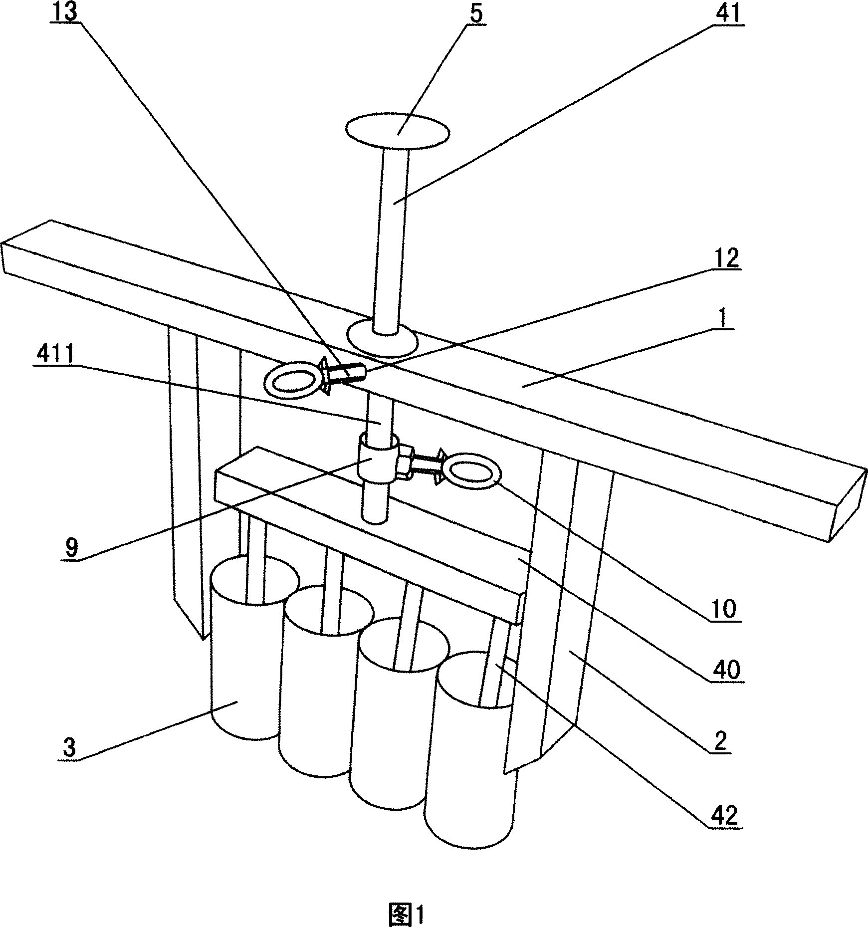
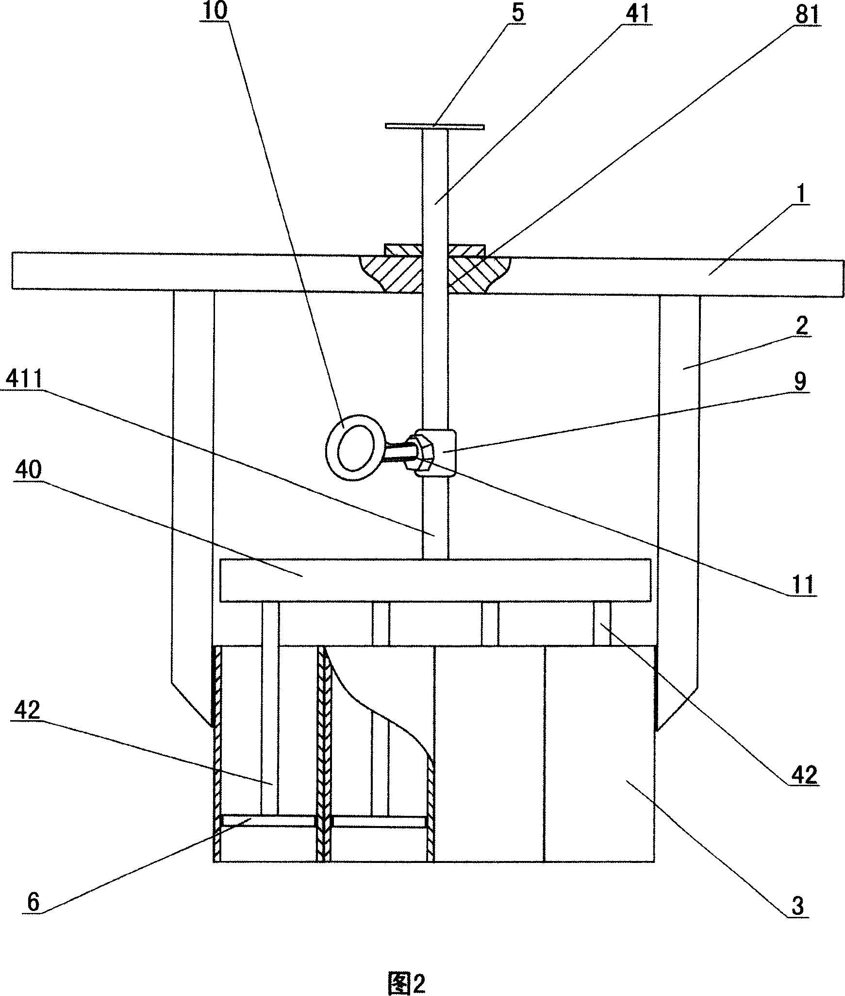
[0033] As shown in Fig. 1 and Fig. 2, a stuffing divider includes a handle base 1, a mold base 2, a barrel 3 and a stuffing pushing mechanism, the above-mentioned handle base 1 is a horizontal bar, and the above-mentioned mold base 2 is two The connecting column arranged vertically, the lower side of the cross bar is fixedly connected with the upper ends of the two connecting columns, the above-mentioned material cylinder 3 is a cylinder, there are four in total, and the four material cylinders 3 are installed between the two connecting columns, that is, each material The barrels 3 are directly fixedly connected side by side, the sides of each barrel 3 are in contact, and the barrels 3 at both ends are respectively fixedly connected to the inner sides of the two connecting columns; The push rod is divided into an upper push rod 41 and several lower push rods 42, the number of the lower push rods 42 is equal to the number of the barrel 3, the lower end of the upper push rod 41 a...
Embodiment 2
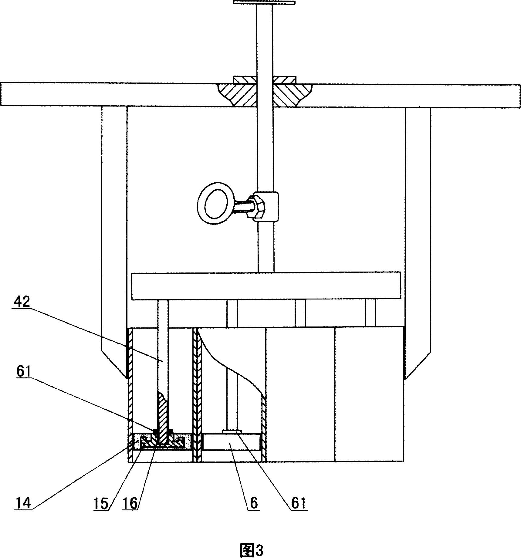
[0038] Embodiment 2 is basically the same as Embodiment 1, the difference between the two is:
[0039] As shown in Figure 3, the pressure sheet 6 in Example 2 is composed of a silica gel sheet 14 and a reinforcement 15, the reinforcement 15 is arranged in the silica gel sheet 14 and is fixedly connected with the silica gel sheet 14, that is, the silica gel sheet 14 is injected on the reinforcement 15 On the outer surface of the reinforcement member 15, a screw hole 16 is provided, and the lower end of the lower push rod 42 is provided with threads, and the lower push rod 42 is connected to the reinforcement member 15 through threads; the above-mentioned lower push rod 42 is provided with a locking nut 61, A lock nut 61 is located on the reinforcement 15 . The above-mentioned silica gel sheet 14 is made of edible silica gel and meets food hygiene requirements. Since the silica gel sheet 14 has the property of not sticking to the stuffing, the processed stuffing can be demoulde...
Embodiment 3
[0041] As shown in Fig. 4 and Fig. 5, a stuffing divider includes a handle base 1, a mold base 2, a barrel 3 and a stuffing pushing mechanism, the above-mentioned mold base 2 is a horizontal bar, and the above-mentioned handle base 1 is a The lugs at both ends of the cross bar, the above-mentioned material cylinders 3 are directly fixedly connected side by side, the upper end of the material cylinder 3 is fixedly connected with the lower side of the middle part of the formwork 2, and the sides of each material cylinder 3 are in contact; the above-mentioned stuffing mechanism includes a push rod 4. Push rod cap 17, pressing piece 6, guide post 18, hand push bar 19 and return spring 20, the number of the above-mentioned push rod 4 is equal to the number of the barrel 3, and the above-mentioned mold frame 2 is provided with a Holes 82, the number of through holes 82 is equal to the number of push rods 4, the push rods 4 can slide through the through holes 82, the upper end of each...
PUM
 Abstract
Description
Claims
Application Information
 - R&D
- Intellectual Property
- Life Sciences
- Materials
- Tech Scout
- Unparalleled Data Quality
- Higher Quality Content
- 60% Fewer Hallucinations
Browse by: Latest US Patents, China's latest patents, Technical Efficacy Thesaurus, Application Domain, Technology Topic, Popular Technical Reports.
© 2025 PatSnap. All rights reserved.Legal|Privacy policy|Modern Slavery Act Transparency Statement|Sitemap|About US| Contact US: help@patsnap.com


