Cyclone separator
The technology of a cyclone and a circulating pipe is applied in the direction of a cyclone device, a device whose axial direction of the cyclone can be reversed, etc., and can solve the problems of instability of the central gas column of the separator, low separation efficiency, and entrainment of aerosols, etc. Achieve the effect of reducing pressure drop, simple structure and improving efficiency
- Summary
- Abstract
- Description
- Claims
- Application Information
AI Technical Summary
Problems solved by technology
Method used
Image
Examples
Embodiment 1
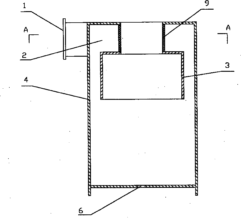
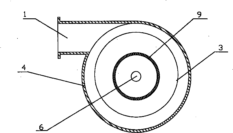
[0031] like figure 1 , figure 2 As shown, a circulation cyclone comprises an outer cyclone 4, the upper part of the outer cyclone 4 is provided with a tangential inlet 1, the lower end of the outer cyclone 4 is provided with a discharge port 6, and the outer cyclone 4 There is an inner swirl cylinder 3, and the upper end cover of the inner swirl cylinder 3 and the upper end cover of the outer swirl cylinder 4 are connected by a circulation pipe 9, and the outer swirl cylinder 4, the inner swirl cylinder 3 and the circulation pipe 9 are connected between A swirl chamber 2 is formed, and the inlet port 1 communicates with the swirl chamber 2 . The separated fluid flows into the swirl chamber 2 from the inlet 1, and then spins around, passes through the annular slit flow channel between the inner swirl cylinder 3 and the upper body of the outer swirl cylinder 4, and spirals down along the lower body of the outer swirl cylinder. The primary separation is performed at the lower ...
Embodiment 2
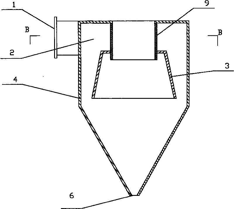
[0033] like image 3 , Figure 4 As shown, a circulation cyclone comprises an outer cyclone 4, the upper part of the outer cyclone 4 is provided with a tangential inlet 1, the lower end of the outer cyclone 4 is provided with a discharge port 6, and the outer cyclone 4 There is an inner swirl cylinder 3, and the upper end cover of the inner swirl cylinder 3 and the upper end cover of the outer swirl cylinder 4 are connected by a circulation pipe 9, and the outer swirl cylinder 4, the inner swirl cylinder 3 and the circulation pipe 9 are connected between A swirl chamber 2 is formed, the inlet 1 is communicated with the swirl chamber 2, the lower part of the circulation pipe 9 extends into the inner swirl cylinder 3, and the inner swirl cylinder 3 has a conical structure with a small upper part and a large lower part. 4. Both the inner swirl cylinder 3 and the circulation pipe 9 are installed coaxially, and the lower part of the outer swirl cylinder 4 has a conical structure w...
Embodiment 3
[0035] like Figure 5 to Figure 7 As shown, a circulation cyclone comprises an outer cyclone 4, the upper part of the outer cyclone 4 is provided with a tangential inlet 1, the lower end of the outer cyclone 4 is provided with a discharge port 6, and the outer cyclone 4 There is an inner swirl cylinder 4, and the upper end cover of the inner swirl cylinder 3 and the upper end cover of the outer swirl cylinder 4 are connected by a circulation pipe 9, and the outer swirl cylinder 4, the inner swirl cylinder 3 and the circulation pipe 9 are connected between A swirl cavity 2 is formed, the inlet 1 is communicated with the swirl cavity 2, and the middle and lower outer walls of the inner swirl cylinder 3 are provided with flow-equalizing blades 5, and the flow-equalizing blades 5 are connected with the inner wall of the outer swirl cylinder 4. The flow vane 5 is an axial vane, and the lower part of the outer swirl cylinder 4 has a conical structure with a large upper and a small l...
PUM
 Abstract
Description
Claims
Application Information
 - R&D
- Intellectual Property
- Life Sciences
- Materials
- Tech Scout
- Unparalleled Data Quality
- Higher Quality Content
- 60% Fewer Hallucinations
Browse by: Latest US Patents, China's latest patents, Technical Efficacy Thesaurus, Application Domain, Technology Topic, Popular Technical Reports.
© 2025 PatSnap. All rights reserved.Legal|Privacy policy|Modern Slavery Act Transparency Statement|Sitemap|About US| Contact US: help@patsnap.com


