Neural net based temperature compensating optical fibre gyroscope

A technology of temperature compensation and neural network, which is applied in the direction of speed measurement by gyro effect, Sagnac effect gyroscope, speed/acceleration/shock measurement, etc. It can solve the problems of temperature phase fluctuation and noise of optical fiber ring, and improve the accuracy, The effect of reducing the amount of gyro calculation and improving the nonlinear mapping ability

Inactive Publication Date: 2007-08-08
BEIHANG UNIV
View PDF0 Cites 47 Cited by
  • Summary
  • Abstract
  • Description
  • Claims
  • Application Information

AI Technical Summary

Problems solved by technology

Due to Shupe noise, the temperature gradient will cause thermally induced non-reciprocal noise and temperature phase fluctuation noise in the fiber ring

Method used


Image

  • Neural net based temperature compensating optical fibre gyroscope
  • Neural net based temperature compensating optical fibre gyroscope

Examples


Embodiment Construction

[0023] The present invention will be further described in detail below in conjunction with the accompanying drawings.

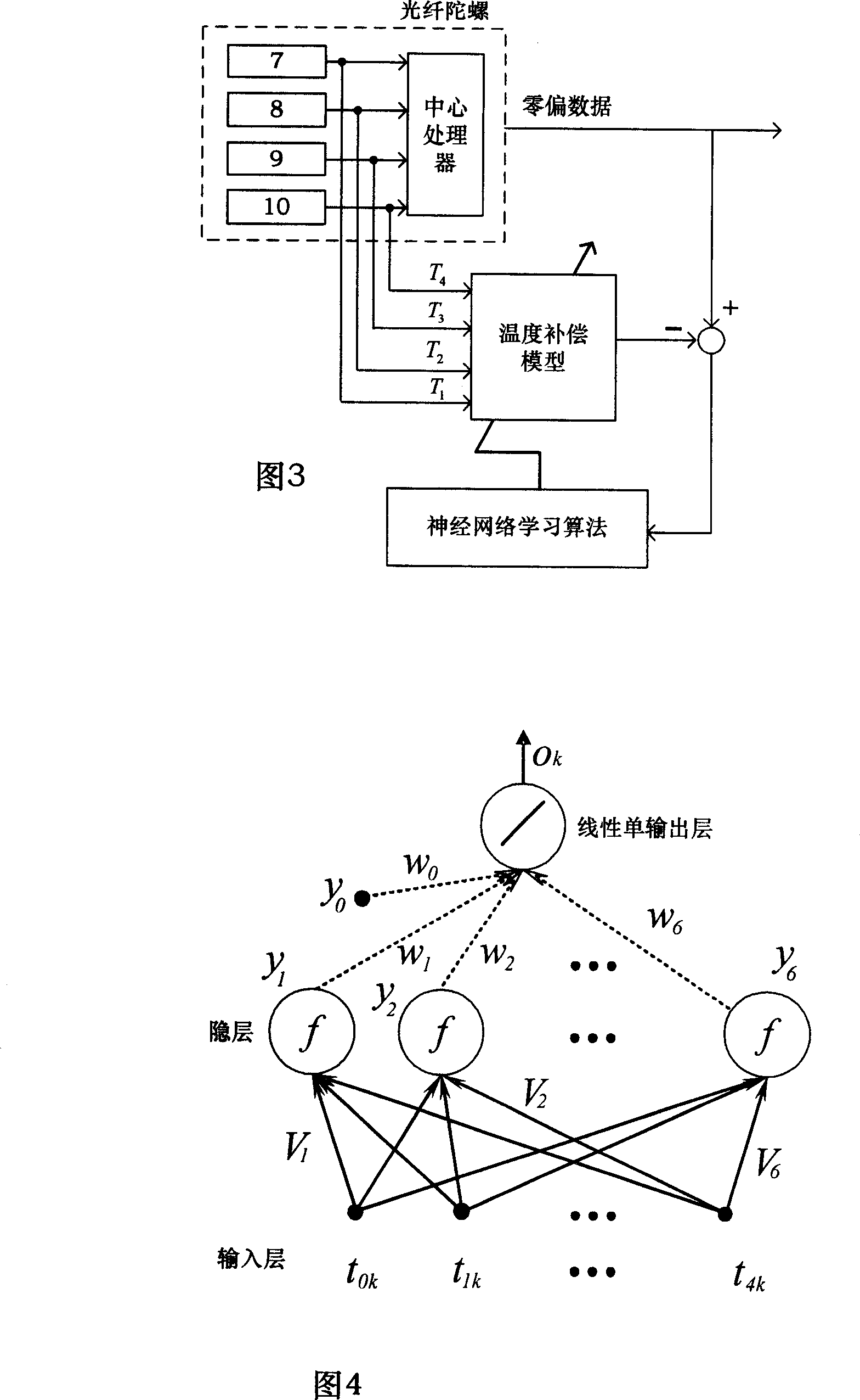
[0024] The present invention is a kind of fiber optic gyroscope for temperature compensation based on neural network, which adopts a neural network learning algorithm for temperature drift compensation. The corrected temperature drift compensation weight coefficient obtained in this way is necessary for the high-precision output of fiber optic gyroscope. parameter.

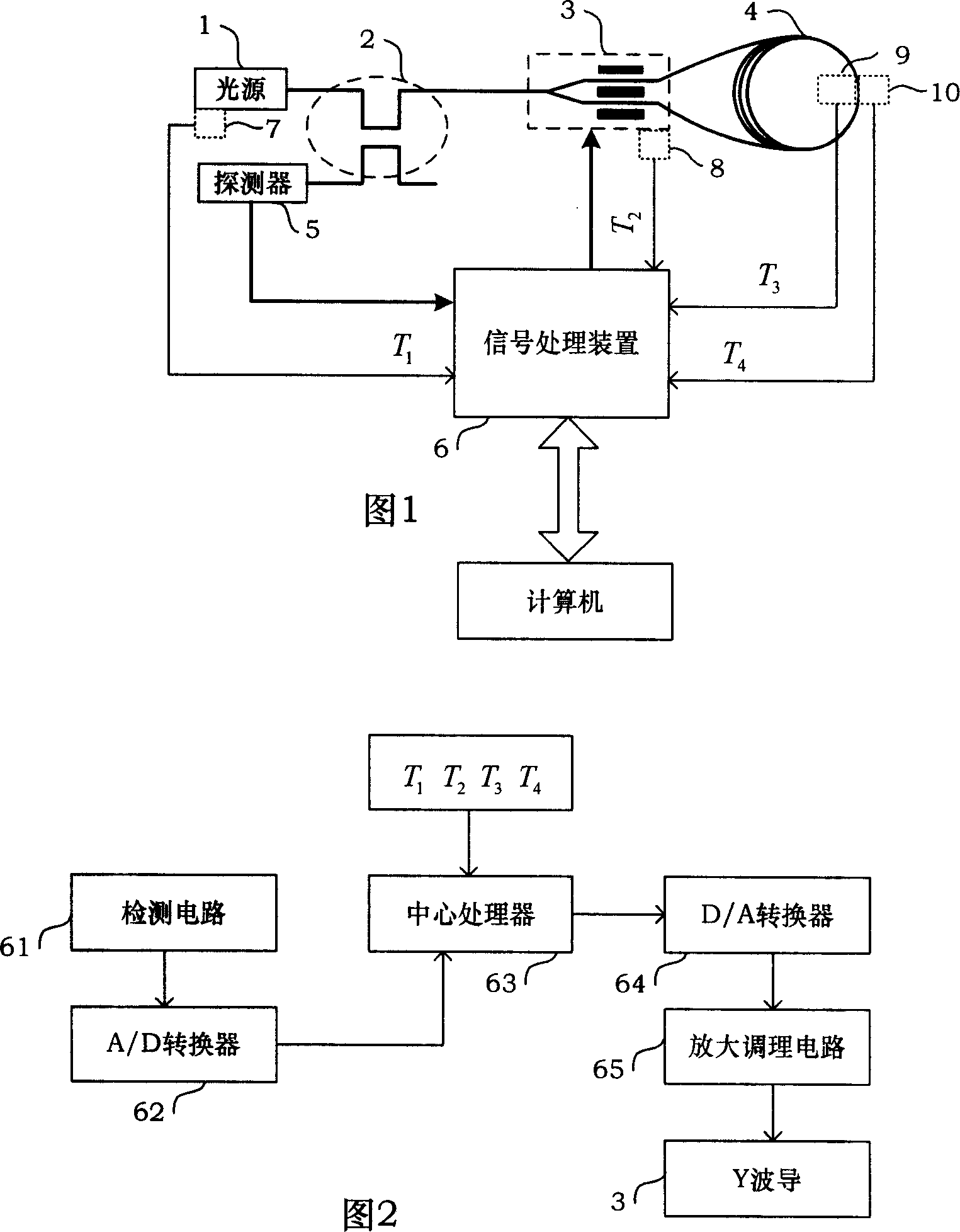
[0025] Please refer to Figure 1, according to the influence of temperature on the output of the fiber optic gyroscope when the fiber optic gyroscope is working, install the temperature sensor A7 at the light source 1, the temperature sensor B8 at the Y waveguide 3, and the temperature sensor C9 and A temperature sensor D10 is installed outside the optical fiber ring 4, and the temperature sensor A7 is used to collect the light source temperature T at the light source 1. 1 , the temperature senso...


PUM


Abstract

The invention discloses an FOG based on neural network to do temperature compensation, using the neural network learning algorithm for the temperature drift compensation method, and the temperature compensation method obtains the amendment temperature compensation coefficient to provide parameters for FOG high precision output. According to the effect of the temperature to the FOG output when the FOG working, it respectively installs a temperature sensor A on the light source, a temperature sensor B at the Y waveguide, a temperature sensor C at the fiber ring inside and a temperature sensor D at the fiber ring outside, and through temperature change of the four temperature sensors, and using the neural network learning algorithm for temperature compensation model training, it makes the built temperature drift compensation having good nonlinear mapping ability, self-learning ability and the generalization ability; the temperature drift compensation coefficient measurement is measured in the debugging phase, reducing the gyro computing volume when using.

Description

technical field [0001] The invention relates to a method for compensating the temperature drift of the output precision of an interference fiber optic gyroscope, more particularly, to a fiber optic gyroscope for temperature drift compensation based on a neural network. Background technique [0002] The interferometric fiber optic gyroscope is an instrument for measuring angular velocity. Its hardware consists of a light source 1, a coupler 2, a Y waveguide 3, an optical fiber ring 4, a detector 5 and a signal processing device 6 (see Figure 1). Described signal processing device 6 comprises the detection circuit 61, A / D converter 62, central processing unit 63, D / A converter 64 and amplification conditioning circuit 65 that are used to detect the optical power signal that detector 5 outputs to form (please See Figure 2). The measurement of the angular velocity of the interference fiber optic gyroscope is characterized by the size of the non-reciprocal phase difference cause...

Claims


Application Information

Patent Timeline
Patent Type & Authority Applications(China)
IPC IPC(8): G01C19/72G01C25/00G01P9/00
Inventor 金靖宋凝芳南书志潘雄李敏
Owner BEIHANG UNIV
Why Eureka
Try Eureka