

Deuterium lamp with striking resistance
A resistance and deuterium lamp technology, applied in the field of deuterium lamps, can solve the problems of poor excitation effect of deuterium lamps, low power supply current energy, low power supply power, etc., and achieve the effect of improving the qualification rate, increasing energy, and ensuring triggering performance.
- Summary
- Abstract
- Description
- Claims
- Application Information
AI Technical Summary
Problems solved by technology
Method used
Image

Examples
Embodiment Construction
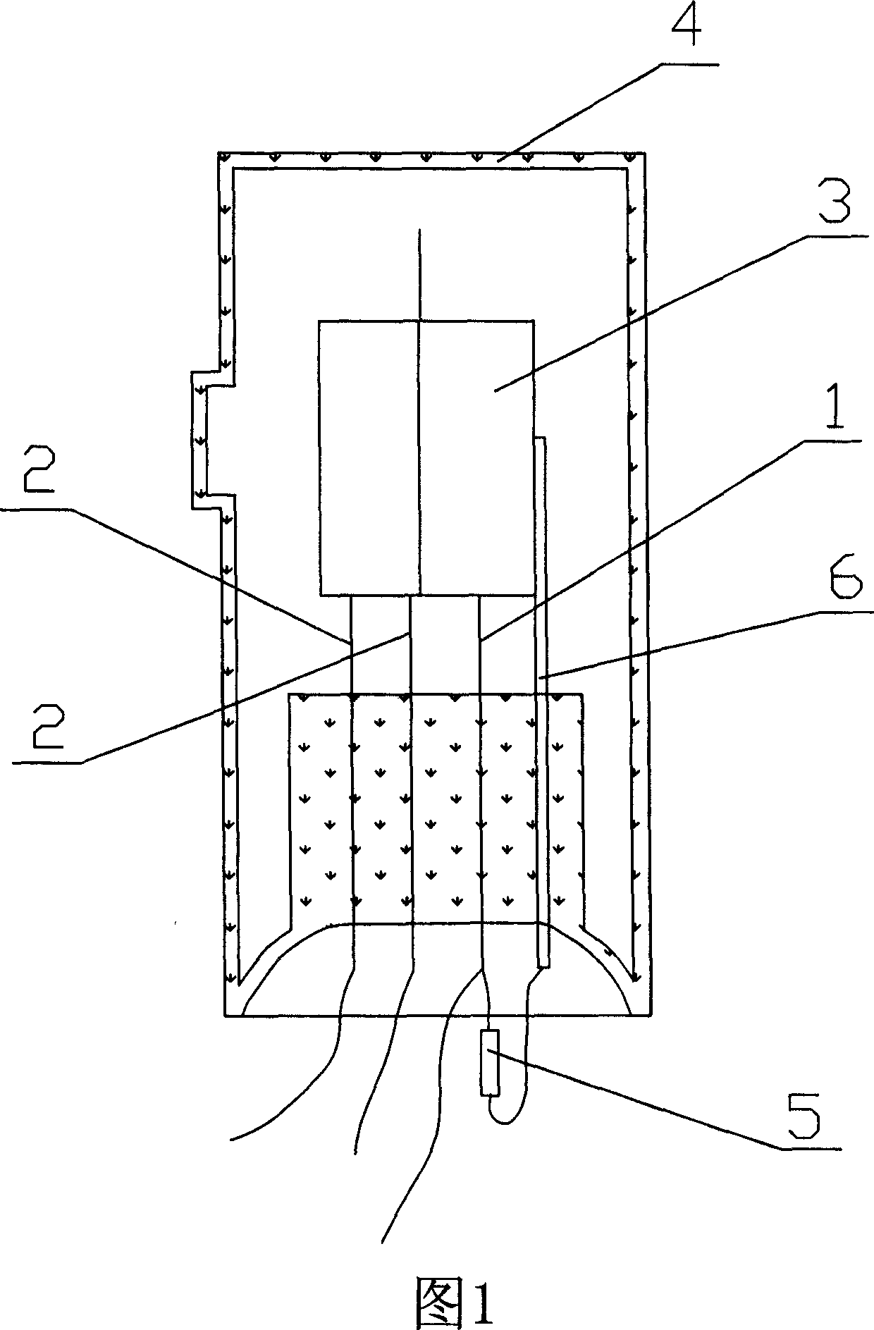
[0013] As shown in the accompanying drawing 1, there is a deuterium lamp cross-sectional structure with a starting resistance, which has a cylindrical transparent glass bulb 4, anode 1, cathode 2, nickel shell 3 and a nickel shell fixing rod 6 for supporting and fixing the nickel shell 3. , extend the nickel shell fixing rod 6 and extend it out of the bulb shell 4, and connect the extension end with the anode 1 at the connection outside the bulb shell 4 with a resistor 5, and the resistance value of the resistor 5 can be selected to be 10-15 kohm .
[0014] In a word, the inventive point of the present invention is only to connect a resistor in series between the anode of the deuterium lamp and the nickel shell, so that the nickel shell is also charged with a positive potential, so that the entire nickel shell becomes a grid, thereby accelerating electrons from the cathode to the nickel shell. The speed of the anode increases the momentum of the electrons, which makes the deut...
PUM
 Abstract
Description
Claims
Application Information