
Device suitable for triggered gap

A technology for triggering gaps and triggers, which is applied to circuits dedicated to spark gaps, spark gaps, spark gap components, etc. It can solve problems such as difficult conduction of the main gap, insufficient pressure in the injection chamber, and affecting the electrical performance of the trigger gap. , to achieve the effect of improving the overall mechanical strength, improving the mechanical strength of the electrode, and improving the flow capacity of the electrode

Active Publication Date: 2017-06-20
CHINA ELECTRIC POWER RES INST +1
View PDF3 Cites 5 Cited by
  • Summary
  • Abstract
  • Description
  • Claims
  • Application Information

AI Technical Summary

Problems solved by technology

The structure of the electrode and its flow-induced magnetic field are the key factors affecting the arc motion characteristics. In SF 6 During the development of the trigger gap, the spiral groove contact structure of the vacuum circuit breaker is often applied directly, which may easily lead to insufficient pressure in the injection chamber, insufficient plasma jet injection height, difficult conduction of the main gap, and long stagnation time of the arc after arcing, which will lead to electrode failure. The central platform is seriously ablated. When the arc moves to the edge of the electrode, it will stagnate again, and there will be obvious melting marks on the edge of the electrode. The above phenomenon will undoubtedly affect the SF 6 Improvement of trigger gap electrical performance

Method used


Image

  • Device suitable for triggered gap
  • Device suitable for triggered gap
  • Device suitable for triggered gap

Examples


Embodiment Construction

[0027] Below in conjunction with accompanying drawing and specific embodiment the present invention is described in further detail:

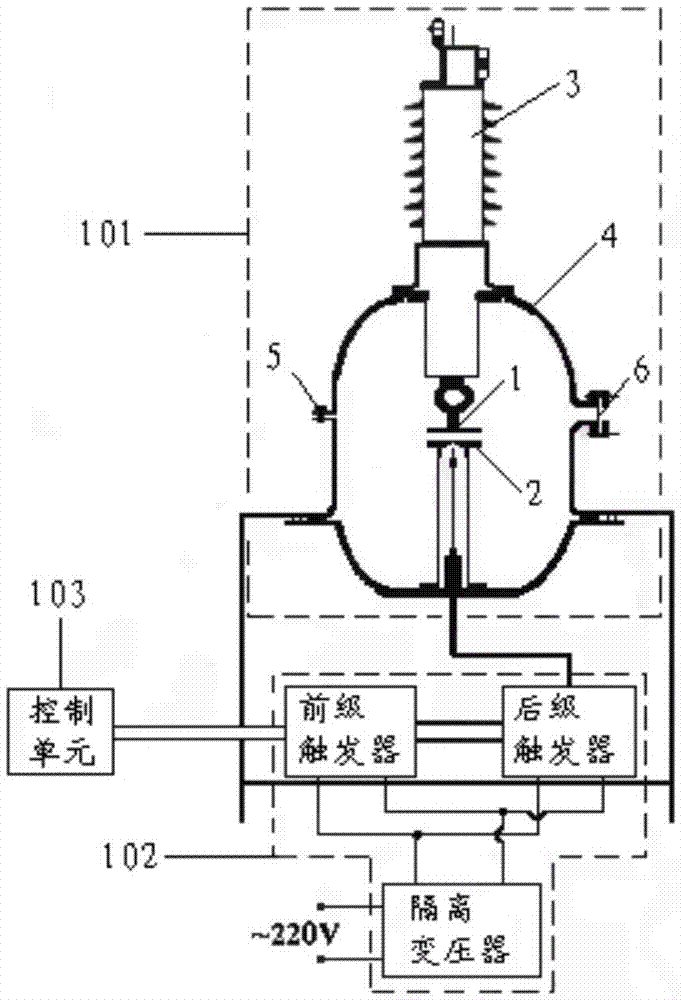
[0028] according to figure 1 As shown, the integral device of the injection trigger gap includes: a trigger gap body 101 , a trigger 102 and a control unit 103 .

[0029] The control unit 103 receives the control signal sent from the outside, converts the control signal into an optical signal, transmits it through an optical fiber, and outputs it to the trigger 102 , and controls the trigger 102 to trigger the conduction of the trigger gap body 101 .

[0030] The trigger 102 includes an isolation transformer, a pre-stage trigger and a post-stage trigger. The isolation transformer supplies power to the front-stage trigger and the rear-stage trigger respectively. After the front-stage trigger receives the trigger signal sent by the control unit 101, it outputs a pulse signal to discharge the rear-stage trigger, generates a high-voltage pulse sign...


PUM


Abstract

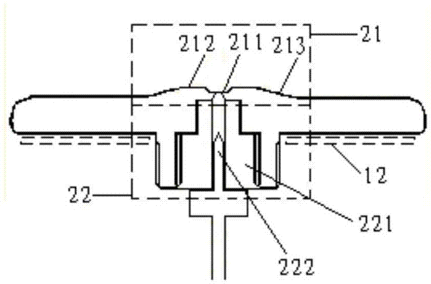
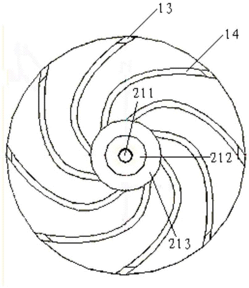
The invention provides a device suitable for a triggered gap. The device comprises a triggered gap body (101), a trigger (102) and a control unit (103). The triggered gap body (101) comprises a high voltage electrode (1) and a ground electrode (2). The ground electrode is provided with a crater-type ground electrode truncated cone structure; the high voltage electrode is provided with a smoothly-transited boss structure; each electrode is provided with edge-overlapped radial arm structures; each electrode is provided with a stainless steel backboard; the crater-type ground electrode truncated cone structure can prevent injection cavity punctures from being ablated, and the trigger performance of the gap is guaranteed; the smooth high voltage electrode boss structure can mitigate ablation of the electric arc to the high voltage electrode central truncated cone, and the electrode flow capacity can be improved; the edge-overlapped radial arm structures can mitigate ablation to edges of the electrodes, and the electrode flow capacity and the whole mechanical strength are improved; and each of the high voltage electrode and the ground electrode is provided with one stainless steel backboard, and the mechanical strength of the electrodes can be further improved.

Description

technical field [0001] The invention relates to a device for triggering gaps, in particular to a large-capacity SF under medium and high pressure levels. 6 Device that triggers the gap. Background technique [0002] In the field of pulse power, with the development of high-power trigger gap technology, the trigger conduction time can be shortened to tens of nanoseconds, the flow capacity can reach thousands of coulombs, and it has a high withstand voltage level. The action time of the trigger gap is much lower than that of conventional switches. It has strong controllability, high technical performance, and is easy to form a fast closing switch. It can be used as a core device to form a special application and solve many long-standing technical problems in the power grid. High power trigger gap is divided into vacuum and SF 6 There are two types of trigger gaps, of which SF 6 Higher voltage levels are available for trigger gaps. [0003] SF 6 The trigger gap mainly reli...

Claims


Application Information

Patent Timeline
Patent Type & Authority Applications(China)
IPC IPC(8): H01T1/22H01T14/00H01T15/00
Inventor 李志兵张鹏飞颜湘莲刘北阳王浩何洁徐晓东
Owner CHINA ELECTRIC POWER RES INST
Learn More