
Vehicle assisted monitoring apparatus and method

A vehicle auxiliary and monitoring device technology, which is applied in the direction of TV, color TV, closed-circuit television system, etc., and can solve the problems of easy damage, no night vision, poor night vision, etc.

Inactive Publication Date: 2007-08-08
IND TECH RES INST
View PDF0 Cites 7 Cited by
  • Summary
  • Abstract
  • Description
  • Claims
  • Application Information

AI Technical Summary

Problems solved by technology

[0004] (1). Angle of view is fixed: because the traditional rearview mirror is a plane mirror, the viewing angle is not large enough. Although in the prior art, most rearview mirrors can be adjusted, but once the adjustment is completed, the angle of view is fixed. Therefore, in some In the case of turning or parking on the side of the road, there is still no way to achieve the effect of dynamic changes
[0005] (2). Poor vision at night: traditional rearview mirrors can only have better visual effects when the visibility is high, but at night or when the visibility is poor (such as dense fog), the reflection of the rearview mirror poor image quality
[0006] (3). Easy to be damaged: the traditional rearview mirror is easily damaged by the impact of external force because it protrudes from the car body. Even if there is a so-called automatic folding technology, it is only limited to the stationary state of the vehicle. Vehicles, still unable to avoid damage caused by external collisions
Although this technology can automatically adjust the monitoring position, it has no night vision function, so it still cannot solve the problem of traditional rearview mirrors at night or in external environments with low visibility

Method used


Image

  • Vehicle assisted monitoring apparatus and method
  • Vehicle assisted monitoring apparatus and method
  • Vehicle assisted monitoring apparatus and method

Examples


Embodiment Construction

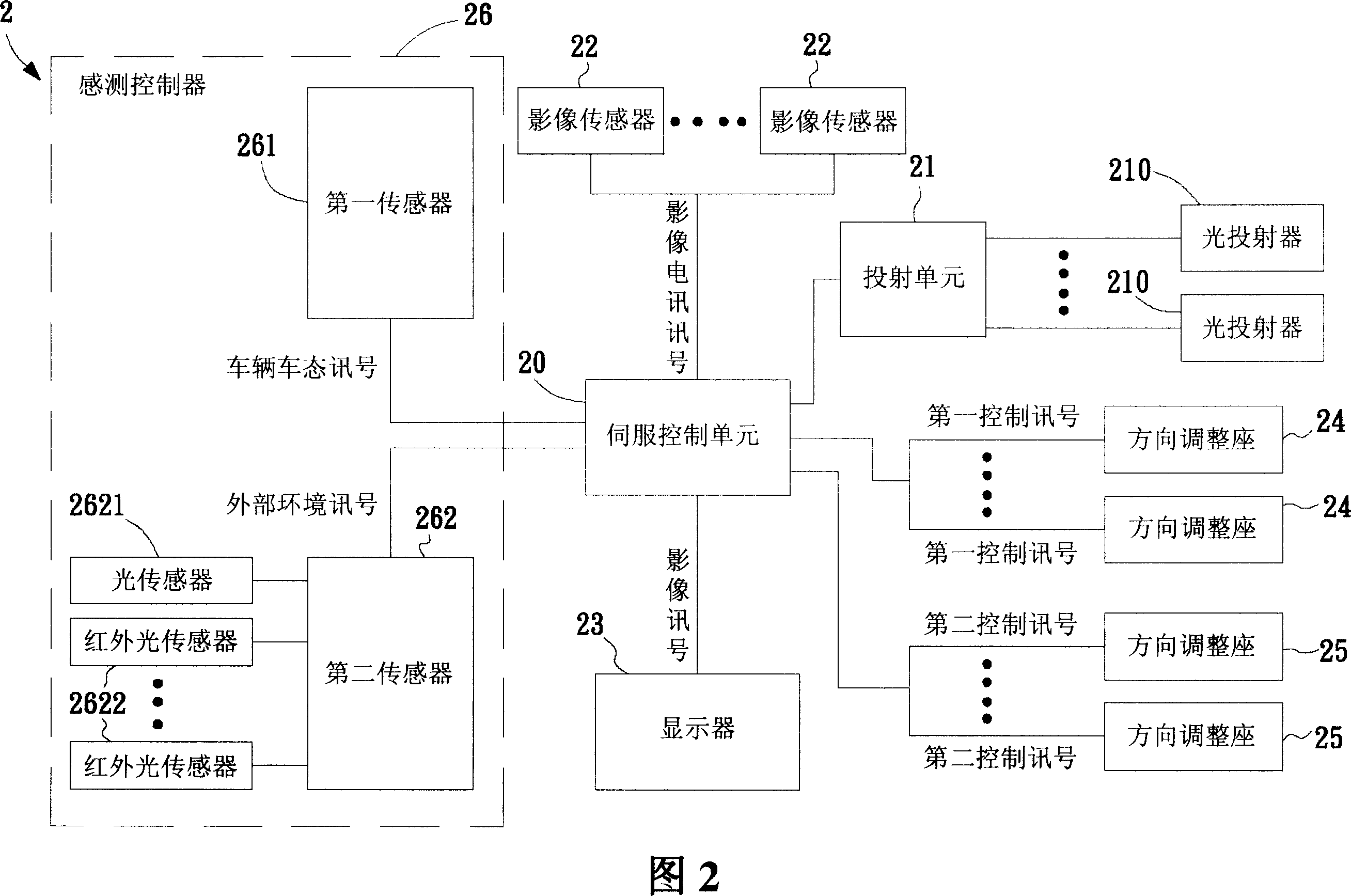
[0060] In order to have a further cognition and understanding of the characteristics, purpose and functions of the present invention, the relevant structure and design concept of the system of the present invention will be described below.

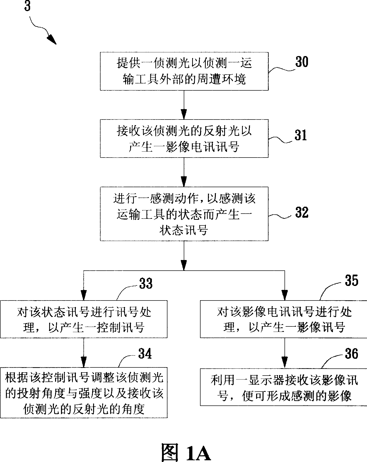
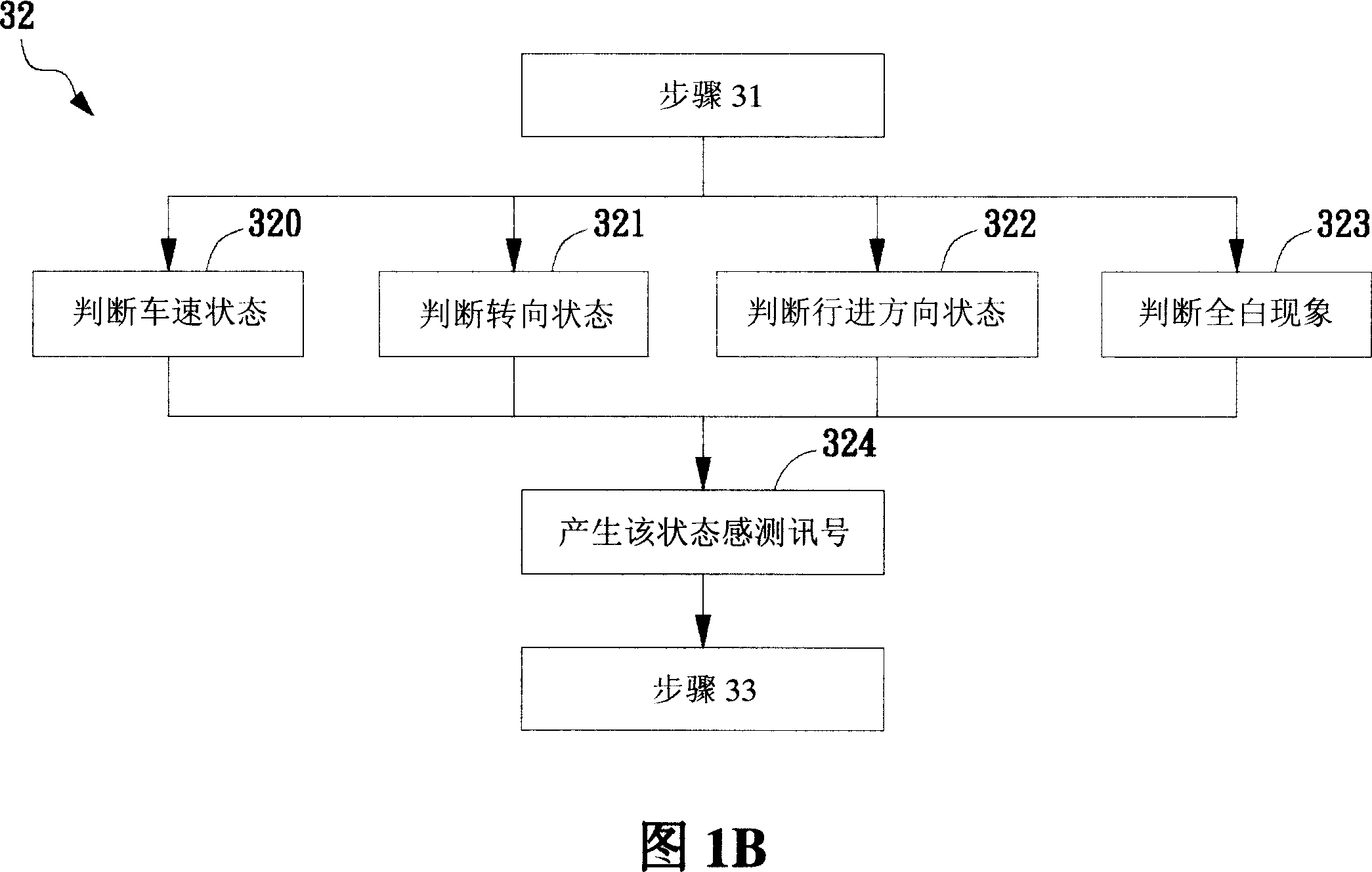
[0061] Please refer to FIG. 1A , which is a schematic flowchart of the vehicle auxiliary monitoring method of the present invention. The monitoring method 3 includes the following steps: firstly, as shown in step 30 , a detection light is provided to detect the surrounding environment outside a vehicle. In this embodiment, the detection light may be one of visible light, infrared light and a combination thereof. Then proceed to step 31, receiving the reflected light of the detection light to generate an image signal. In this embodiment, the device for receiving the detection light can be a charge-coupled device (CCD) or a complementary metal oxide semiconductor (CMOS). As a component for sensing images.

[0062] Then proceed to step 32 ,...


PUM


Abstract

The invention relates to one car aid monitor method, which comprises the following steps: providing one detection light for one commission tool outer environment; receiving the detection light reflection light to generate one image signal; processing one sensor operation for the tool to generate one status signal; processing status signals to generate one control signals; according to control signal to adjust projection angle and to receive the reflection angle. The invention also provides one car aid monitor device.

Description

technical field [0001] The present invention relates to a monitoring device and method, in particular to a method of using detection light to sense the condition of the surrounding environment of the vehicle to display an image and to control the projection of the detection light by sensing the state of the vehicle and the surrounding environment And the receiving angle of reflected light to reduce dead angle and avoid the vehicle auxiliary monitoring device and method of all white phenomenon. Background technique [0002] Vehicles are an important product of the development of human civilization. In addition to facilitating human life and shortening the traffic between the two places, of course it also drives the development and progress of industry. With the advancement of science and technology, the technical evolution of vehicles is also changing with each passing day. However, in the structure of vehicles, there are still some parts that have not escaped from the tradit...

Claims


Application Information

Patent Timeline
IPC IPC(8): H04N7/18H04N5/225
Inventor 廖永盛杜文卿
Owner IND TECH RES INST
Learn More