A cutter device for tobacco products

A cutting device, a technology of tobacco products, applied in the direction of tobacco, application, and paper cigarette manufacturing, which can solve the problems of output loss, time loss, etc.

Inactive Publication Date: 2011-04-20
GD SPA
View PDF0 Cites 0 Cited by
  • Summary
  • Abstract
  • Description
  • Claims
  • Application Information

AI Technical Summary

Problems solved by technology

[0016] From the above it is evident that in order to restore the timing between the blade and counter-blade, but also to check and if necessary correct the tension of the drive belt, a stop must be stopped; overall hourly output loss

Method used


Image

  • A cutter device for tobacco products
  • A cutter device for tobacco products
  • A cutter device for tobacco products

Examples


Embodiment Construction

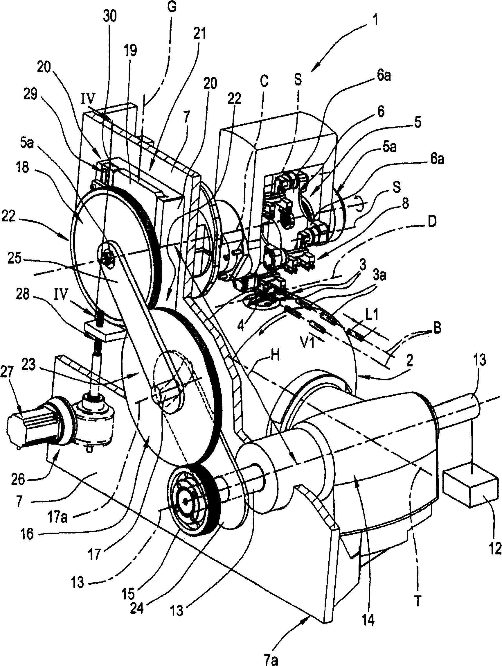
[0026] Referring to the accompanying drawings, numeral 1 generally denotes a cutting device for tobacco products according to the present invention.

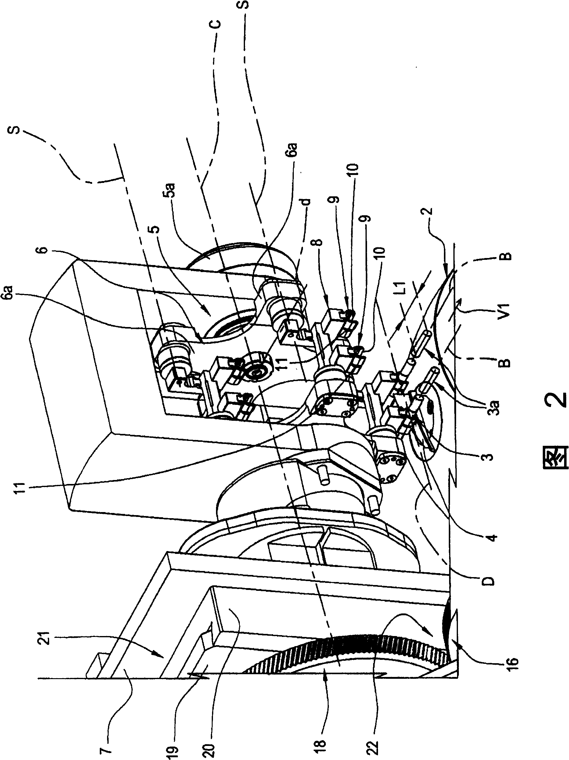
[0027] The device 1 comprises a cutting drum 2, such as figure 1 As shown, the cutting drum 2 rotates in a counterclockwise direction about an axis T which is angled or skewed with respect to the feed direction B followed by at least one continuous tobacco or filter rod 3 . In the preferred embodiment in the figure, more precisely, as figure 1 2 and 2, the two continuous rods 3 advance towards the device 1 parallel to each other along the feed direction B at a predetermined and constant speed denoted V1.

[0028] The cutting drum 2 comprises two peripheral and diametrically opposite blades 4 (only one of the two blades can be seen in the figures), by which two continuous rods 3 are severed and A given angular velocity is divided into rods 3a of a predetermined length denoted L1.

[0029] The axis T of the drum and thus the in...


PUM


Abstract

A cutter device in a cigarette maker comprises a drum (2) turning on a first axis (T), by which two continuous cigarette rods (3) advancing along a feed direction (B) are cut into sticks (3a), also a counterblade (5) turning on a second axis (C) extending transversely to the feed direction (B) and separated from the rods (3) by a distance dictated by the length of the cut sticks (3a); the cutter drum (2) and the counterblade (5) are interconnected by a train of three gears (15, 16, 18) of which the axes of rotation are linked in pairs by way of two connecting rods (24, 25) in such a way that the gears (15,16,18) can be maintained in constant meshing contact when the counterblade axis (C) is repositioned relative to the feed direction (B). The connecting rods (24, 25) thus provide a timingmechanism able to synchronize the operation of the cutter drum (2) and the counterblade (5), which remains unaffected by changes in the distance between the axis of rotation (C) of the counterblade (5) and the path of the cigarette rods (3).

Description

technical field [0001] The invention relates to a cutting device for tobacco products. Background technique [0002] Manufacturing systems used in the tobacco industry include machines by which continuous cigarette or filter rods are first formed and then cut transversely into discrete rods of predetermined length. [0003] In the case of a cigarette maker, for example, a continuous cigarette rod is divided by cutting means into individual cigarette rods, each cigarette rod being then associated with a filter tip to produce a filter cigarette. [0004] The cutting device of the prior art design, positioned along the feed path followed by the continuous rod, the cutting device comprises a cutter head, and an impact assembly or counterblade, the cutter head is mounted to a relatively rotatable shaft, and Usually equipped with two diametrically opposed blades, causing the blades to interact with the striker assembly or counterblade, which includes a rotor mechanically connecte...

Claims


Application Information

Patent Timeline
Patent Type & Authority Patents(China)
IPC IPC(8): A24C5/28A24D3/02B26D1/12B26D5/08B26D7/26
CPCB26D7/01B26D3/16B26D1/28A24C5/28
Inventor V·斯瑞格诺利L·巴拉蒂E·瑟伦
Owner GD SPA
Why Eureka
Try Eureka