Elevator

A technology of elevators and elevator cars, applied in the field of elevators, can solve the problems of cost increase, stop operation, and difficulty in distinguishing normal slippage, etc., and achieve the effect of cost increase and high reliability

A technology of elevators and elevator cars, applied in the field of elevators, can solve the problems of cost increase, stop operation, and difficulty in distinguishing normal slippage, etc., and achieve the effect of cost increase and high reliability

CN101016134AActive Publication Date: 2007-08-15HITACHI LTD

Image

  • Elevator
  • Elevator
  • Elevator

Examples


Embodiment Construction

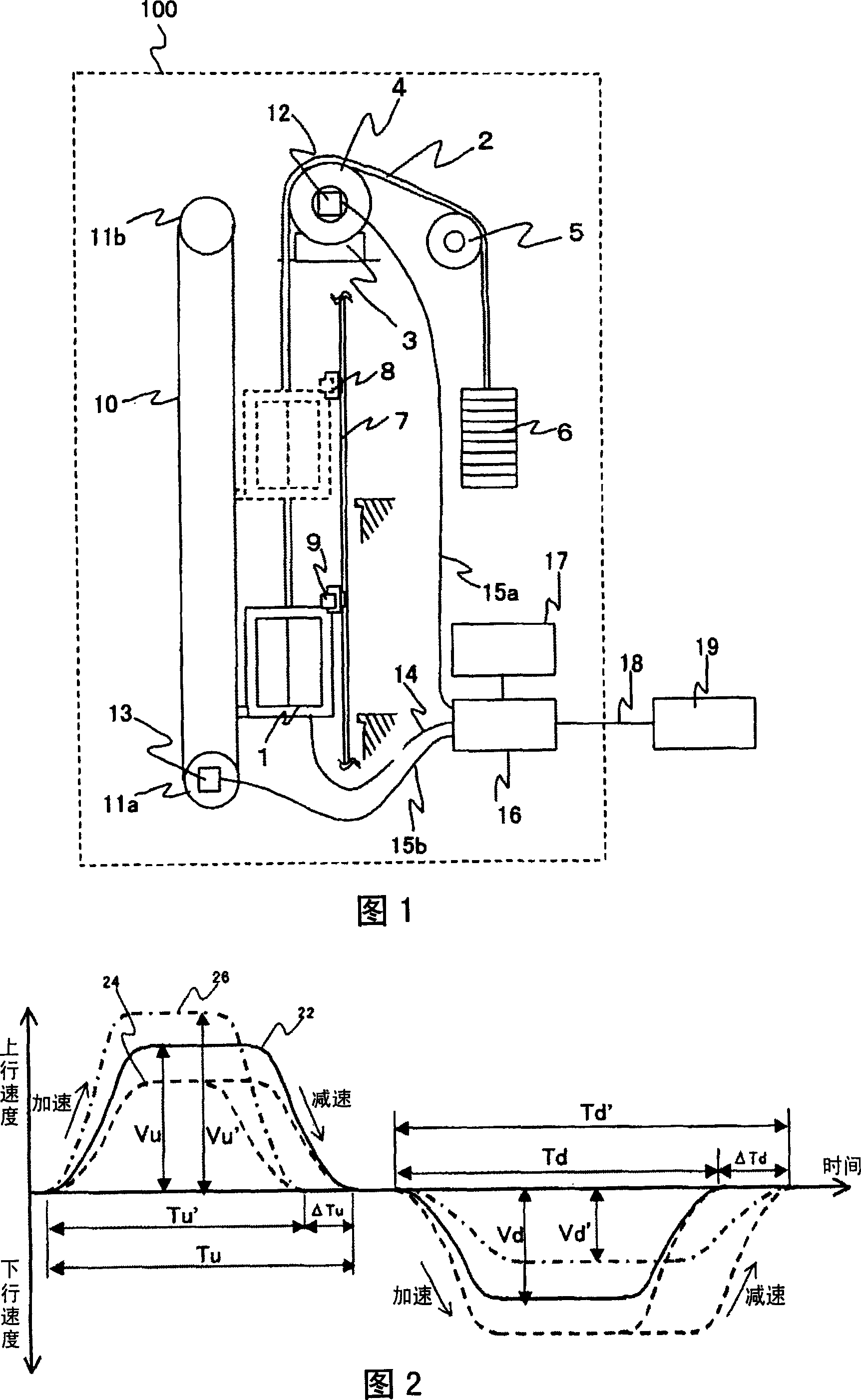
[0044] Hereinafter, the elevator of the present invention will be described with reference to the accompanying drawings. FIG. 1 is a schematic diagram of one embodiment of an elevator 100 . In the elevator 100 , an elevator car 1 is connected to one end of a rope 2 , and a counterweight 6 is connected to the other end of the rope 2 . The middle portion of the sling 2 is wound around a sheave 4 mounted on a driving device 3 arranged above the elevator car 1 and a deflection pulley 5 separated from the sheave 4 . s position. A sheave encoder 12 for detecting the rotation amount of the sheave 4 is attached to the sheave 4 .

[0045] The elevator car 1 is arranged in the hoistway, and a guide rail 7 is installed on the side wall of the hoistway. The elevator car 1 ascends and descends in the hoistway under the guidance of the guide rail 7 . Shielding plates 8 are installed on the guide rails 7 at positions corresponding to the respective floors. In addition, a position detect...


PUM


Abstract

The invention provides an elevator, which can easily evaluate deterioration of a rope and a sheave in the elevator. In the rope type elevator 100, a car 1 and a counter weight 6 are connected by the rope 2. The sheave 4 attached with the rope is rotated / driven by a motor to lift the car. A position detector 9 measures a speed of the car from the time when it passes between shutting off plates 8, 8 installed so as to be separated by a predetermined distance and a clearance of the shutting off plates. In a memory means possessed by an operation part 16, a relationship of a car speed and deterioration of the rope or the sheave is stored and the deterioration of the rope or the sheave is determined with reference to the memory means.

Description

technical field [0001] The invention relates to an elevator, in particular to a device used in the elevator for detecting abnormality of a sheave. Background technique [0002] An example of a conventional elevator is disclosed in Japanese Patent Application Laid-Open No. 2001-262482 of Patent Document 1. In the elevator equipment disclosed in this gazette, in order to reduce the diameter of the elevator sheave, a plurality of wire bundles constituting the cable sling are covered with resin, and the entire cable sling is covered with resin. In an elevator using such a resin-coated wire rope, aging of the resin increases the hardness of the resin, thereby reducing the coefficient of friction between the rope and the sheave. [0003] For this reason, it is necessary to regularly check the amount of slippage between the sling and the sheave and perform maintenance. Japanese Patent Application Laid-Open No. 7-10412 of Patent Document 2 discloses a method for detecting the amou...

Claims


Application Information

Patent Timeline
15 Aug 2007
Publication
CN101016134A
IPC
B66B9/00; B66B5/00; B66B3/00
Inventors
前田太一; 岩仓昭太