Driving device for crank arm type sewing mechine

A driving device, sewing machine technology, applied in sewing machine control devices, sewing machine components, sewing equipment and other directions, can solve the problems of high cost, complex structure, many types of parts, etc., and achieve the effect of preventing misoperation accidents and shortening the shaft length.

Active Publication Date: 2007-08-15
株式会社飞马
View PDF1 Cites 6 Cited by
  • Summary
  • Abstract
  • Description
  • Claims
  • Application Information

AI Technical Summary

Problems solved by technology

[0004] However, in the conventional crank arm type warp let-off sewing machine drive device, since the transmission shaft supported on the bracket of the table is divided, one transmission shaft is connected to the main shaft of the sewing machine, and the other transmission shaft is connected to the motor shaft. , so there are many types of parts, the cost is high, and the structure is also complicated

Method used


Image

  • Driving device for crank arm type sewing mechine
  • Driving device for crank arm type sewing mechine
  • Driving device for crank arm type sewing mechine

Examples


Embodiment Construction

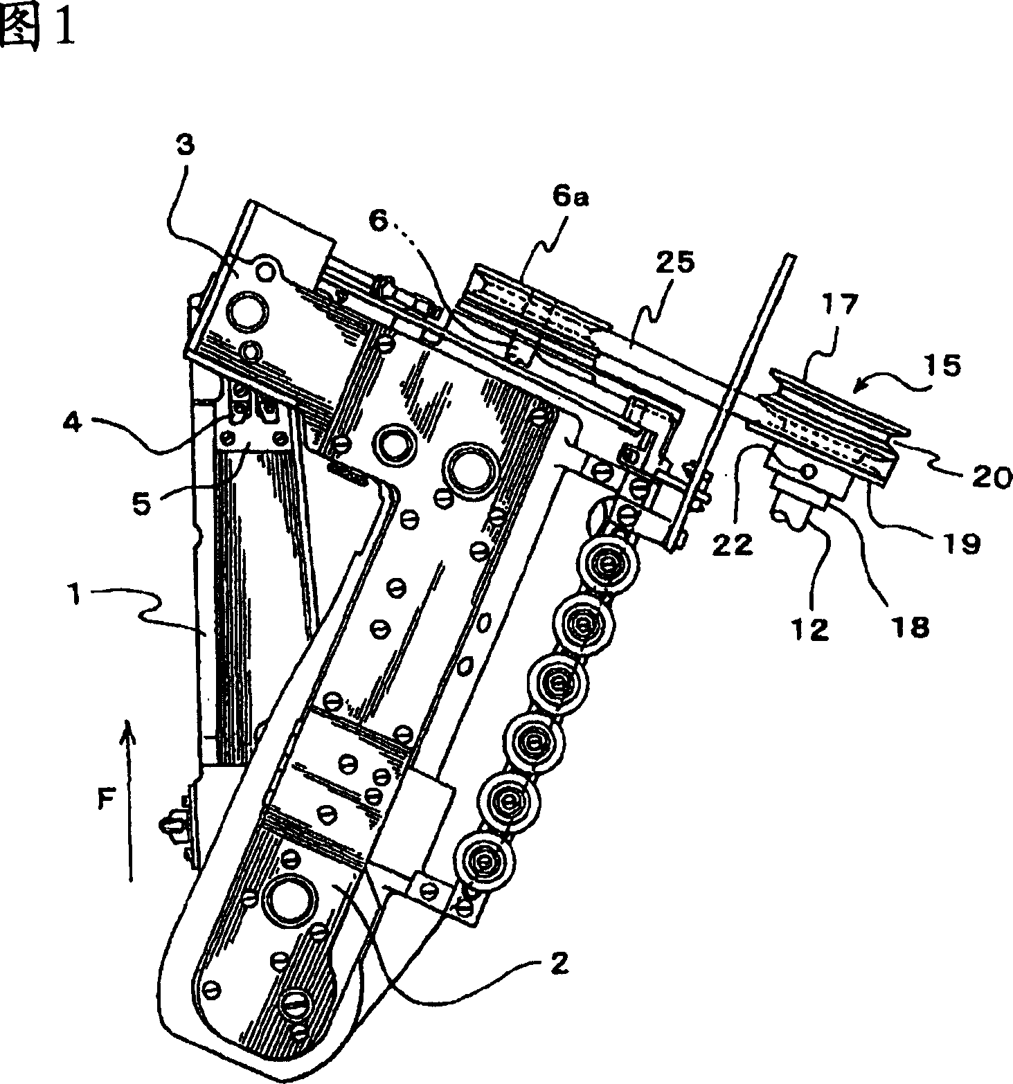
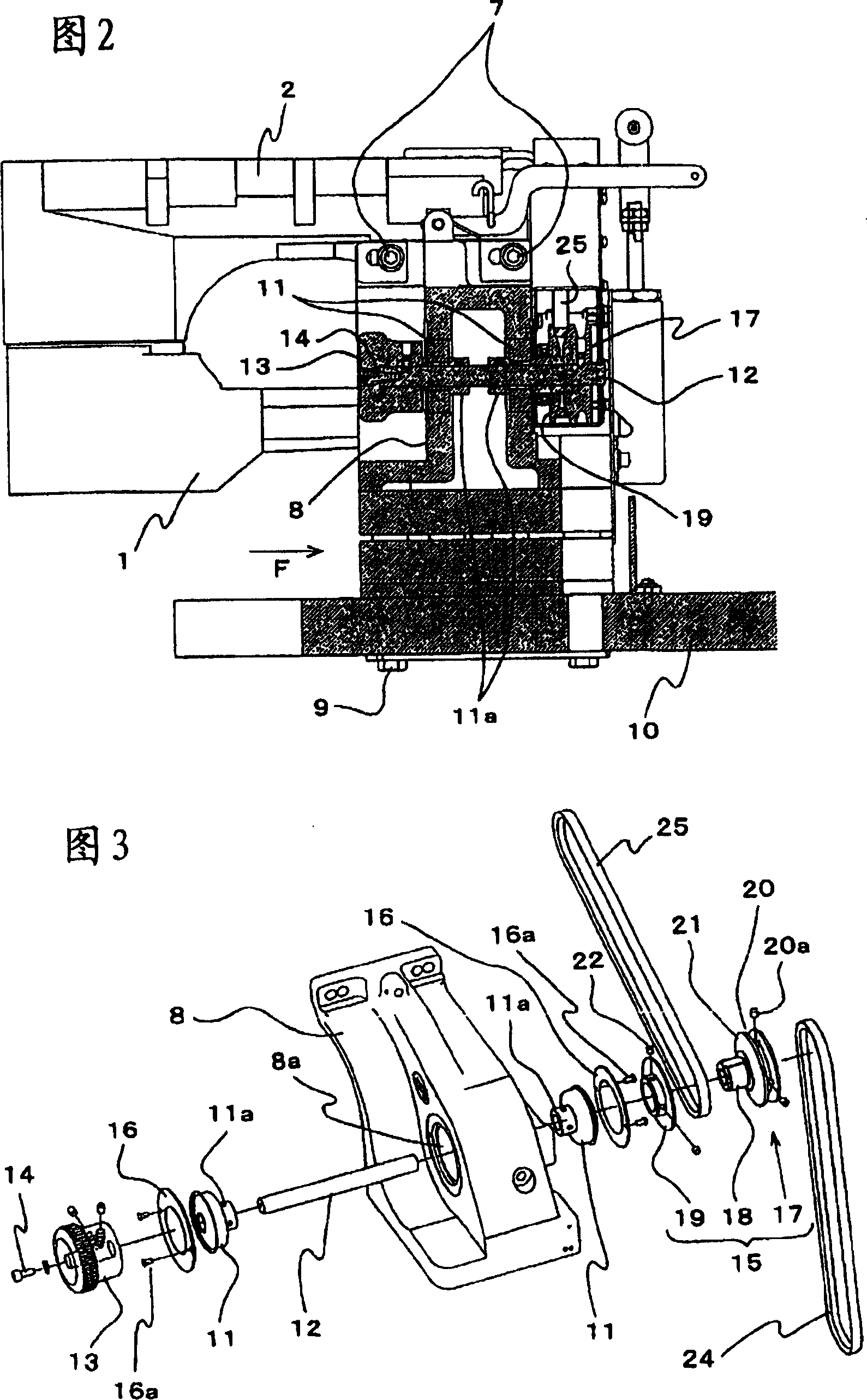
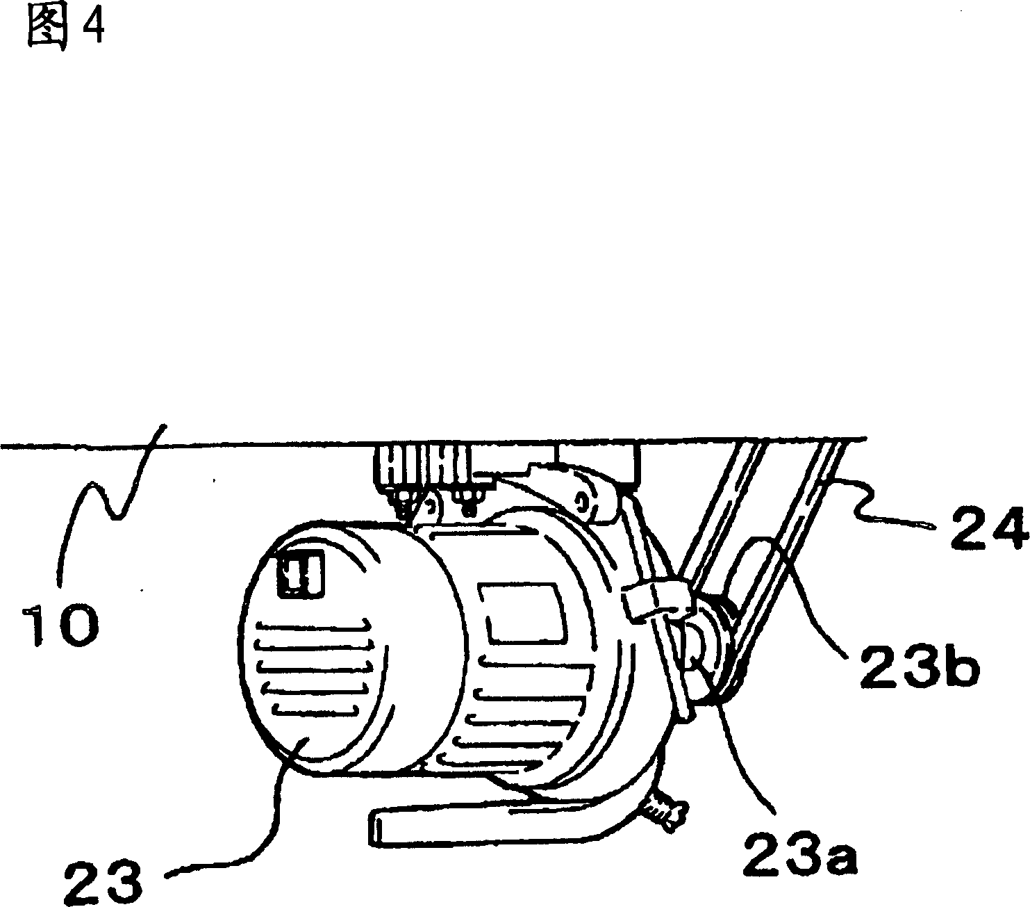
[0032] Embodiments of the present invention will be described below with reference to the drawings. The machine base 1 extends along the cloth feeding direction F, and the base end of the machine base 1 is connected with the horizontal arm 2 . As shown in FIG. 1 , the horizontal arm 2 extends obliquely relative to the machine base 1 , and has a head 3 at its front end. The head 3 has a needle drive mechanism and a presser foot mechanism, and the presser foot 4 of the presser foot mechanism is biased toward the needle plate 5 on the machine base 1 by a spring (not shown). A spindle 6 is pivotally supported on the horizontal arm 2 . The main shaft 6 is arranged along the length direction of the horizontal arm 2 , and one end of the main shaft 6 protrudes outward from the horizontal arm 2 . The horizontal arm 2 is fixed on the bracket 8 by screws 7 , and the bracket 8 is fixed on the workbench 10 by screws 9 .

[0033] A through hole 8a is formed through the bracket 8, and the...


PUM


Abstract

A driven device of crankweb feeding sewing machine, wherein main shaft is supported by axises on level arm extending along the skew direction; transmission shaft is supported by axises on bracket fixing the level arm on the working table, and has manual turn knob on ends; driven motor is located near the working table; cyclic belt combines with the fixed pulley on the transmission shaft to transfer rotation of motor shaft to main shaft, the pulley comprises flange main part, support guide apparatus, and second inclined tablet, wherein, the flange main part comprises first groove and first inclined tablet connecting to the groove and and forming axes. The support guide apparatus and the flange main part are formed together. The second inclined tablet is located opposited to the first inclined tablet, and movably fixed on the support guide apparatus. First groove and second groove which forms by the two inclined tablets combines with different cyclic belts, wherein, one of the cyclic belts is located on the main shaft, and the other cyclic belt is located on the motor shaft.

Description

technical field [0001] The present invention relates to a drive device for a curved arm type let-off sewing machine. Background technique [0002] As a drive device of a conventional crank arm type let-off sewing machine, a drive device that connects the main shaft of the sewing machine to the drive motor via a transmission shaft pivotally supported on the bracket of the table is known (for example, refer to Patent Document 1. ). [0003] [Patent Document 1] Specification of US Patent No. 2960050 (page 2-3, Fig. 1-8) [0004] However, in the conventional crank arm type warp let-off sewing machine drive device, since the transmission shaft supported on the bracket of the table is divided, one transmission shaft is connected to the main shaft of the sewing machine, and the other transmission shaft is connected to the motor shaft. , so there are many types of parts, the cost is high, and the structure is also complicated. [0005] Therefore, an object of the present inventio...

Claims


Application Information

Patent Timeline
Patent Type & Authority Applications(China)
IPC IPC(8): D05B69/00
CPCD05B69/12D05B69/30D05D2205/32
Inventor 引口省三
Owner 株式会社飞马
Why Eureka
Try Eureka