Variable distribution porous end face mechanical sealing structure

A mechanical seal, hole end face technology, applied in the direction of engine seal, mechanical equipment, engine components, etc., can solve the problems of weak pressure resistance, poor dynamic pressure effect, easy to seize, etc., to achieve strong dynamic pressure effect, The effect of increasing the withstand voltage and increasing the blocking effect

Active Publication Date: 2007-08-15
ZHEJIANG UNIV OF TECH
View PDF9 Cites 53 Cited by
  • Summary
  • Abstract
  • Description
  • Claims
  • Application Information

AI Technical Summary

Problems solved by technology

[0003] In order to overcome the disadvantages of poor wear resistance, weak pressure resistance, easy seizure, poor dynamic pressure effect, and large leakage under high parameter conditions in the prior art, the present invention provides an excellent wear resistance, Strong pressure resistance, strong anti-seizing ability, good dynamic pressure effect, small leakage, suitable for variable distribution porous end face mechanical seal structure with high parameters (high temperature, high pressure or high speed)

Method used


Image

  • Variable distribution porous end face mechanical sealing structure
  • Variable distribution porous end face mechanical sealing structure
  • Variable distribution porous end face mechanical sealing structure

Examples


Embodiment 1

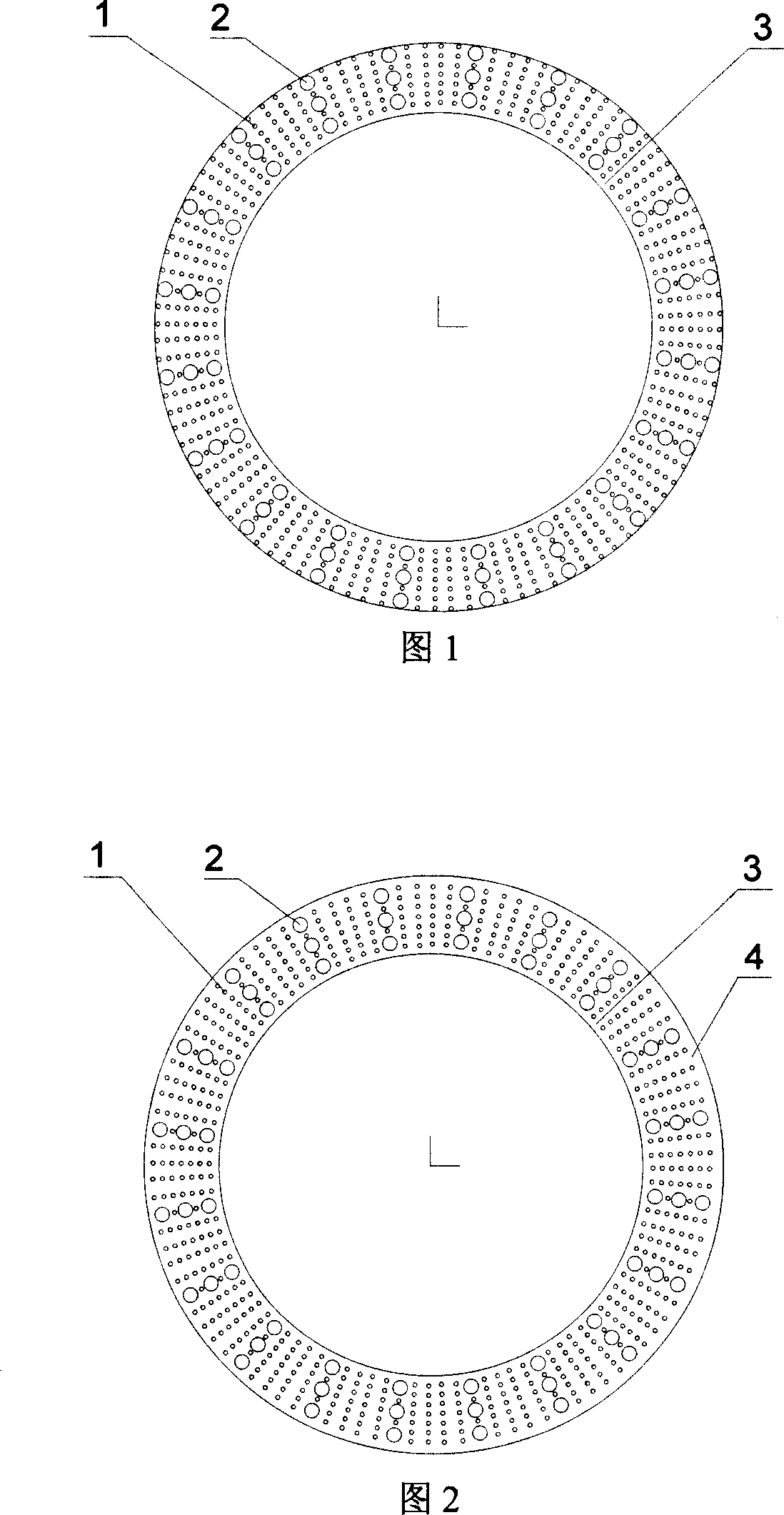
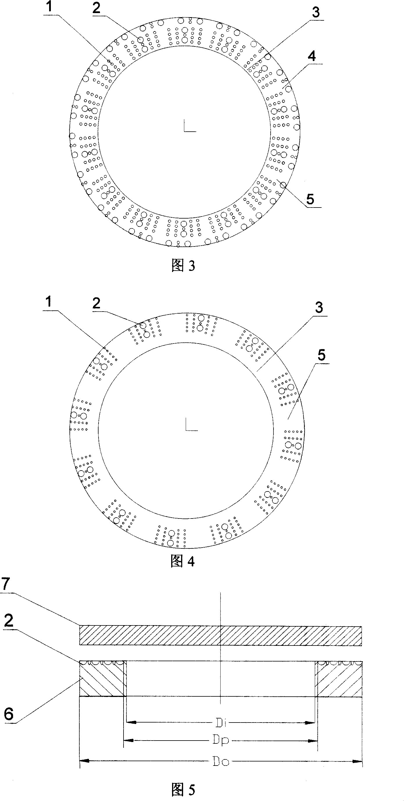
[0040] See Figure 1 and Figure 5: A variable distribution porous end face mechanical seal structure, including the moving ring, static ring and other related parts of the mechanical seal, the sealing end faces of the moving ring and the static ring are bonded to form a circular sealing end face , one side of the ring-shaped sealing end face is the high-pressure side, that is, the upstream side, and one side of the ring-shaped sealing end face is the low-pressure side, that is, the downstream, and the sealing end face of the moving ring or the static ring is open There are micropores, the micropores are of different sizes, and are arranged symmetrically on the sealing end face. The downstream of the microporous ring is provided with an annular sealing dam (3) according to the center symmetry of the end face. The end face of the sealing dam is smooth. surface.

[0041] The micropores are divided into larger micropores (2) and smaller micropores (1). The smaller micropores and th...

Embodiment 2

[0047] See Fig. 1 and Fig. 6: the hole depth of the larger micropore in the upstream first hole ring zone is equal to the depth of the smaller micropore, and the larger micropore gradually decreases along the medium leakage direction, and it is the last one in the downstream. The depth of the larger micropores in the ring zone is not less than 2 μm.

[0048] The remaining structures and implementation modes of this embodiment are the same as those of Embodiment 1.

Embodiment 3

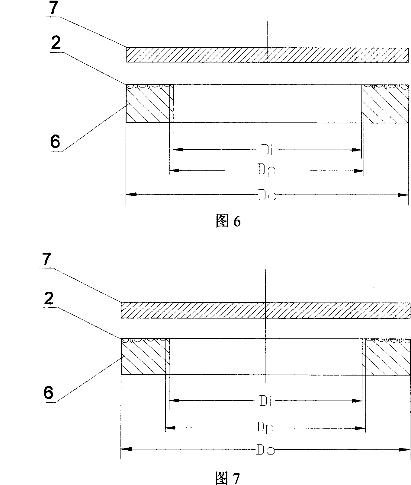
[0050] See Figure 1 and Figure 7: The pore depths of the larger micropores and smaller micropores decrease slightly along the medium leakage direction, and the minimum pore depth or the pore depth of the last pore ring zone downstream is not less than 2 μm.

[0051] The remaining structures and implementation modes of this embodiment are the same as those of Embodiment 1.


PUM


Abstract

The invention relates ton a variable-distribution porous end mechanical sealing structure, comprising a movable ring and a stable ring which are mechanically sealed, to form an annular sealing end. One side of the sealing end is high pressure side as ascending, while another end is low pressure side as descending, at least one sealing end is disposed with porous structure in different sizes symmetry distributed on the sealed end. Compared with present screw or groove mechanical sealing structure, the invention has better pressure resistance, abrasion resistance and better dynamic pressure effect on fluid membrane, to improve the carrier ability of fluid membrane.

Description

(1) Technical field [0001] The invention belongs to an end face sealing device of a rotating shaft, and is a shaft end sealing device of various types of rotary fluid machines such as compressors, expanders, separators, pumps and reactor stirrers. (2) Background technology [0002] The known single-face hydrodynamic pressure or static pressure or dynamic and static pressure combination type mechanical end face seal also has some shortcomings, such as spiral groove hydrodynamic pressure type end face seal (see Lubrication Engineering, 1990, 46 (9): pp607; USA Patent 4,290,611 and USA Patent 20020093141 and Chinese patents 03134193.4 and 96108614.9), although it has low friction power consumption, the leakage is greater than that of ordinary end face seals of the same specification; another example is a porous or dimple end face with the same geometric size Sealing, whether it is the sealing of the whole surface opening (see Tribology Transactions, 1996, 39 (3): pp677 and USA ...

Claims


Application Information

Patent Timeline
Patent Type & Authority Applications(China)
IPC IPC(8): F16J15/34
Inventor 彭旭东李纪云盛颂恩白少先
Owner ZHEJIANG UNIV OF TECH
Why Eureka
Try Eureka