Internal stabilized electromagnetic suspension ring-shaped micro-rotating gyroscope

A technology of electromagnetic suspension and annular rotor, applied in the field of gyroscope in the field of micro-electromechanical technology, can solve the problems of increasing mutual interference, failing to achieve high-precision micro-gyroscope, increasing the complexity of control circuit, etc. Effect

Inactive Publication Date: 2007-08-15
SHANGHAI JIAO TONG UNIV
View PDF1 Cites 13 Cited by
  • Summary
  • Abstract
  • Description
  • Claims
  • Application Information

AI Technical Summary

Problems solved by technology

The planar coil series electromagnetic levitation micro-rotating gyroscope has the following disadvantages: 1. Two high-frequency currents with different frequencies need to pass through the series coil, which increases the complexity of the control circuit; 2. Stable levitation drive electromagnetic field and rotation drive The electromagnetic fields overlap in space, thus increasing the mutual interference between them; 3. The rotating electromagnetic field is distributed in the entire radius and length direction, but the rotating electromagnetic field at the larger radius plays the most role
This speed is far from meeting the requirements of high-precision micro-gyro

Method used


Image

  • Internal stabilized electromagnetic suspension ring-shaped micro-rotating gyroscope
  • Internal stabilized electromagnetic suspension ring-shaped micro-rotating gyroscope

Examples


Embodiment Construction

[0012] The embodiments of the present invention are described in detail below in conjunction with the accompanying drawings: the present embodiment is implemented on the premise of the technical solution of the present invention, and detailed implementation methods and processes are provided, but the protection scope of the present invention is not limited to the following implementations example.

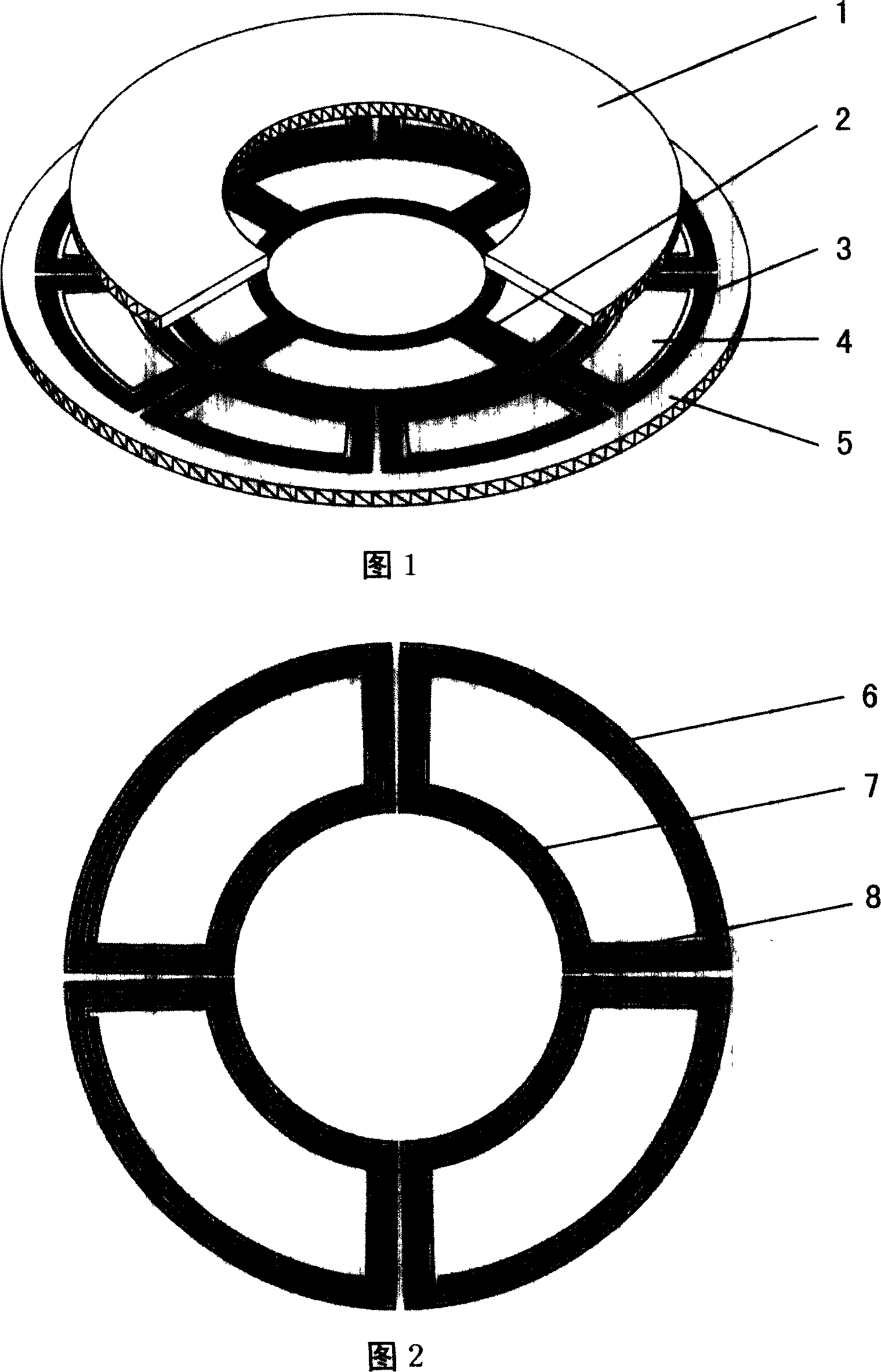
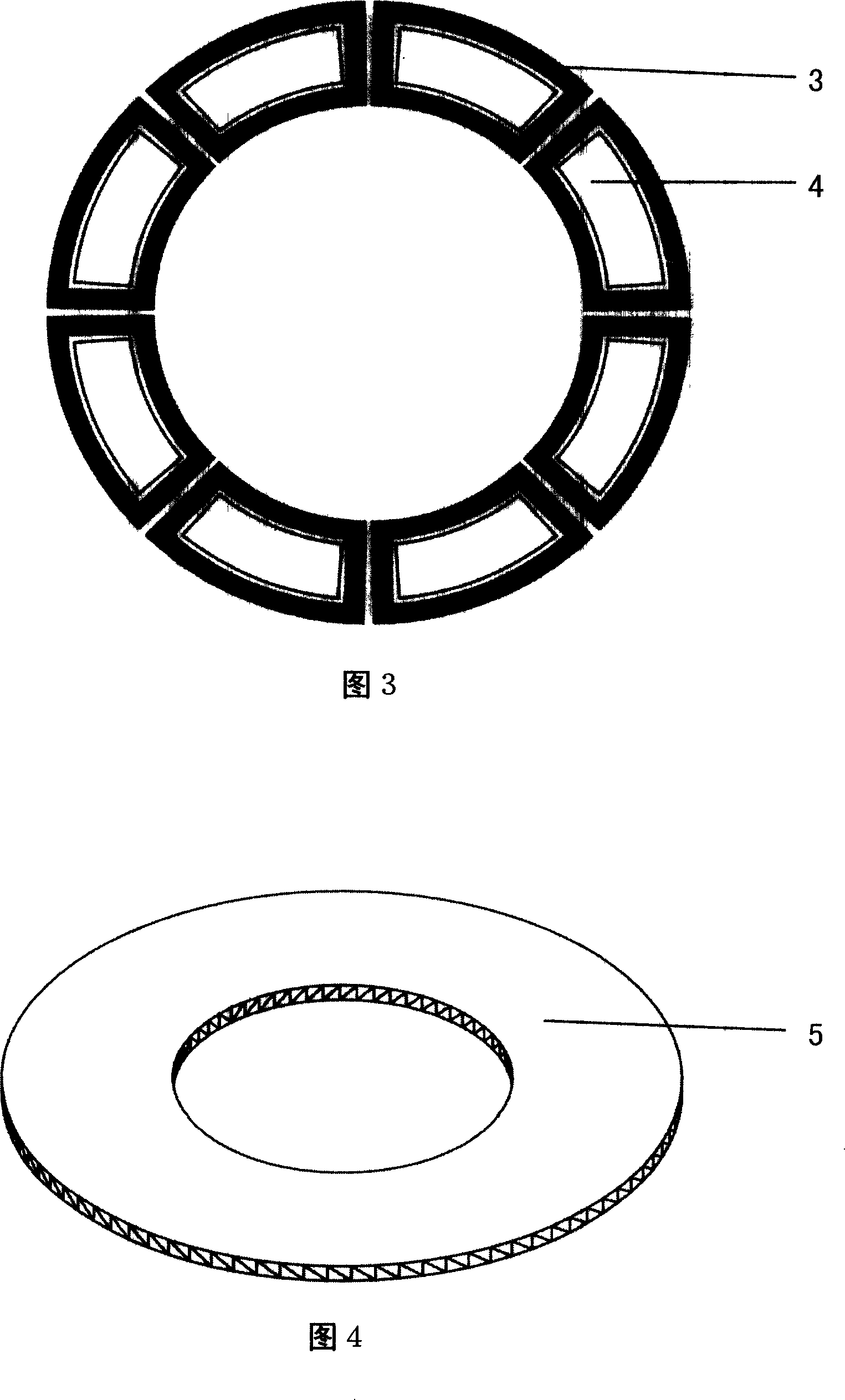
[0013] As shown in FIG. 1 , this embodiment includes: a micro-rotor 1 , a stable levitation coil 2 , a rotating coil 3 , a sensing electrode 4 , and a substrate 5 . As shown in FIG. 2 , the stable levitation coil 2 is composed of three parts: the outer ring 6 of the stable levitation coil, the inner ring 7 of the stable levitation coil, and the connecting wire 8 . The connection relationship is: the stable levitation coil 2, the rotating coil 3, and the sensing electrode 4 are all set on the base 5, forming a fixed connection with the base 5, the micro-rotor 1 is suspended above th...


PUM


Abstract

This invention relates to one inner stable hanging ring rotor micro rotation top in micro machine system technique field, wherein, setting the stable float coil, rotation coil and sensor electrode onto base to form fix connection and base; micro rotor is floating one the base under electronic magnetic force and the ring rotor is under function of hanging coil force to get stable hanging outside rotation coil to generate rotation magnetic field; micro rotor is under rotation magnetic field to generate rotation torque for high speed rotation through sensor electrode.

Description

technical field [0001] The invention relates to a gyroscope in the field of micro-electromechanical technology, in particular to a micro-rotating gyroscope with an internally stable electromagnetic levitation ring rotor. Background technique [0002] In the past two decades, micro-vibration gyroscopes with various structures have been processed by surface micro-processing technology or bulk micro-processing technology of silicon at home and abroad, but it is difficult for micro-vibration gyroscopes to reach the high level of traditional gyroscopes due to various reasons. precision. In the 1990s, Shearwood and others proposed an electromagnetic levitation micro-rotating gyroscope. The electromagnetic levitation micro-rotating gyroscope is composed of planar coils, induction electrodes and micro-rotors. The planar coils are divided into suspension coils according to their functions. , rotating coil and stable coil. The electromagnetic levitation micro-rotating gyroscope is s...

Claims


Application Information

Patent Timeline
Patent Type & Authority Applications(China)
IPC IPC(8): G01C19/24H02K7/09
Inventor 吴校生陈文元赵小林
Owner SHANGHAI JIAO TONG UNIV
Why Eureka
Try Eureka