Double-drive single-swing head for vertical machining center

A technology of vertical machining center and single swing head, which is applied in the direction of metal processing equipment, metal processing machinery parts, driving devices, etc. The effect of moving and avoiding the problem of twisting and deformation of the shaft

Pending Publication Date: 2021-01-05
NINGBO HAITIAN PRECISION MASCH CO LTD
View PDF0 Cites 4 Cited by
  • Summary
  • Abstract
  • Description
  • Claims
  • Application Information

AI Technical Summary

Problems solved by technology

At present, the driving mode of the single pendulum head on the market is mainly mechanical, and generally adopts worm gear or rack and pinion transmission. Although it has good economy, the structure is relatively heavy, the speed is generally not high, and the dynamic characteristics are poor.

Method used


Image

  • Double-drive single-swing head for vertical machining center
  • Double-drive single-swing head for vertical machining center
  • Double-drive single-swing head for vertical machining center

Examples


Embodiment 1

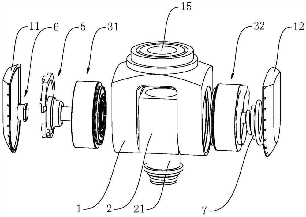
[0022] The double-drive single-swing head for the vertical machining center in Embodiment 1, as shown in the figure, includes the swing head box 1, the spindle box 2, the main shaft 21, and the A-axis left drive assembly 31 installed in the swing head box 1, A-axis right drive assembly 32, A-axis oil separator assembly 5, A-axis encoder assembly 6, A-axis hard limit junction and main shaft pipeline outlet unit. Installed upright on the headstock 2, the lower end of the main shaft 21 protrudes from the main headstock 2, the A-axis left drive assembly 31 and the A-axis right drive assembly 32 are symmetrically arranged on both sides of the headstock 2, and the A-axis left drive assembly 31 includes a left The torque motor assembly and the left hydraulic clamping mechanism, the A-axis right drive assembly 32 includes the right torque motor assembly and the right hydraulic clamping mechanism, the left torque motor assembly and the right torque motor assembly are used to provide dri...

Embodiment 2

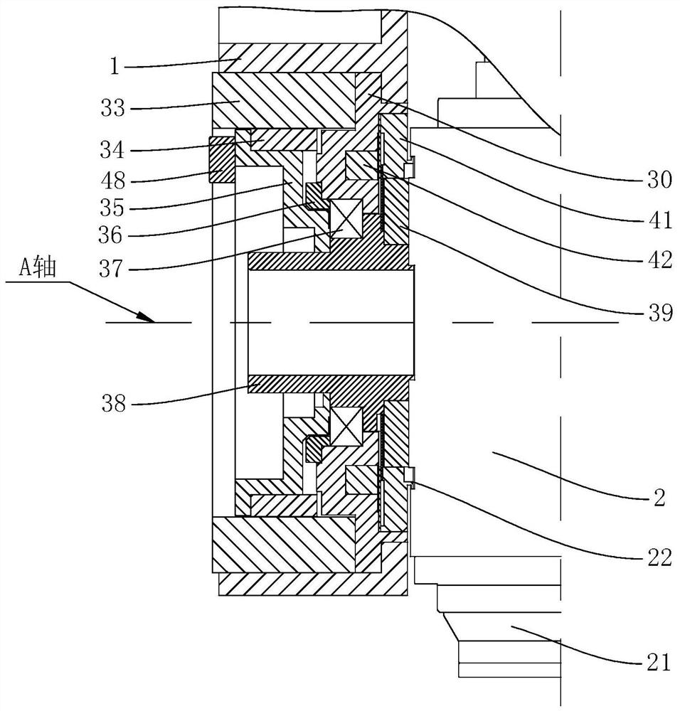
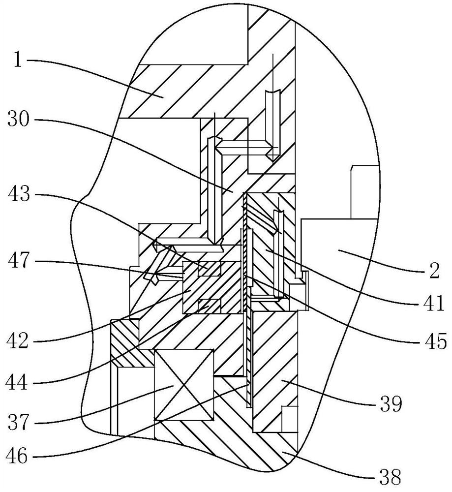
[0028] The vertical machining center of embodiment 2 uses a double drive and single swing head. The difference from embodiment 1 is that in embodiment 2, a leak structure is provided between the bearing seat 30 and the swing head box 1, and the oil drain structure includes a connected The first oil passage 81 and the second oil passage 82, the first oil passage 81 is opened on the side wall of the bearing seat 30, the second oil passage 82 is opened on the side wall of the swing head box 1, the first oil passage 81 and the The gap between the bearing seat 30 and the outer brake pad 45 communicates, and the second oil passage 82 communicates with the outside world.


PUM


Abstract

The invention discloses a double-drive single-swing head for a vertical machining center. The double-drive single-swing head for the vertical machining center comprises a swing head box body, a main shaft box, a main shaft, an A-axis left driving assembly, an A-axis right driving assembly, an A-axis oil distributor assembly, an A-axis encoder assembly and a main shaft pipeline outlet unit. The A-axis left driving assembly comprises a left torque motor assembly and a left hydraulic clamping mechanism. The A-axis right driving assembly comprises a right torque motor assembly and a right hydraulic clamping mechanism. A main shaft pipeline spirally surrounds the main shaft pipeline outlet unit, and a left protective cover and a right protective cover are fixed to the left side and the right side of the swing head box body respectively. According to the double-drive single-swing head, the main shaft box is driven by the double-torque motors which are symmetrically designed, larger rotatingtorque can be provided, high dynamic characteristics and stability required by machining are guaranteed, and the problem that a rotating shaft is distorted and deformed in a traditional single-side driving mode is solved. Meanwhile, the double hydraulic clamping mechanisms are adopted, larger locking torque can be provided, the braking effect can be ensured, and the rigidity of the single swing head in the machining process is ensured.

Description

technical field [0001] The invention relates to a machining center accessory, in particular to a double-drive single-swing head for a vertical machining center. Background technique [0002] The single swing head provides one more degree of freedom for the machine tool, and provides an excellent one-stop solution for multi-angle machining parts. It is an important part of high-end CNC machine tools. At present, the driving mode of the single pendulum head on the market is mainly mechanical, and generally adopts worm gear or rack and pinion transmission. Although it has good economy, the structure is relatively bulky, the speed is generally not high, and the dynamic characteristics are poor. Contents of the invention [0003] The technical problem to be solved by the present invention is to provide a double-drive single-swing head for a vertical machining center that can ensure the high dynamic characteristics and stability required for machining. [0004] The technical so...

Claims


Application Information

Patent Timeline
Patent Type & Authority Applications(China)
IPC IPC(8): B23Q5/10
CPCB23Q5/10
Inventor 汪旭光盛孝勇谢瑞木孙杰梁夷升王弘毅李奕轩
Owner NINGBO HAITIAN PRECISION MASCH CO LTD
Why Eureka
Try Eureka