Biochemical substance sensing method and biosensor optical sensing structue

A technology of biosensors and sensing methods, applied in biological testing, fluorescence/phosphorescence, material inspection products, etc., can solve the problems that are not easy to convert into practical instruments, and the operation of optical waveguide biosensors is not easy. The effect of simultaneous detection of channels to avoid coupling loss

Inactive Publication Date: 2007-08-15
李坚
View PDF0 Cites 11 Cited by
  • Summary
  • Abstract
  • Description
  • Claims
  • Application Information

AI Technical Summary

Problems solved by technology

[0009] Optical waveguide biosensors are not easy to operate, and a lot of work only stays in th...

Method used


Image

  • Biochemical substance sensing method and biosensor optical sensing structue
  • Biochemical substance sensing method and biosensor optical sensing structue

Examples


Embodiment 1

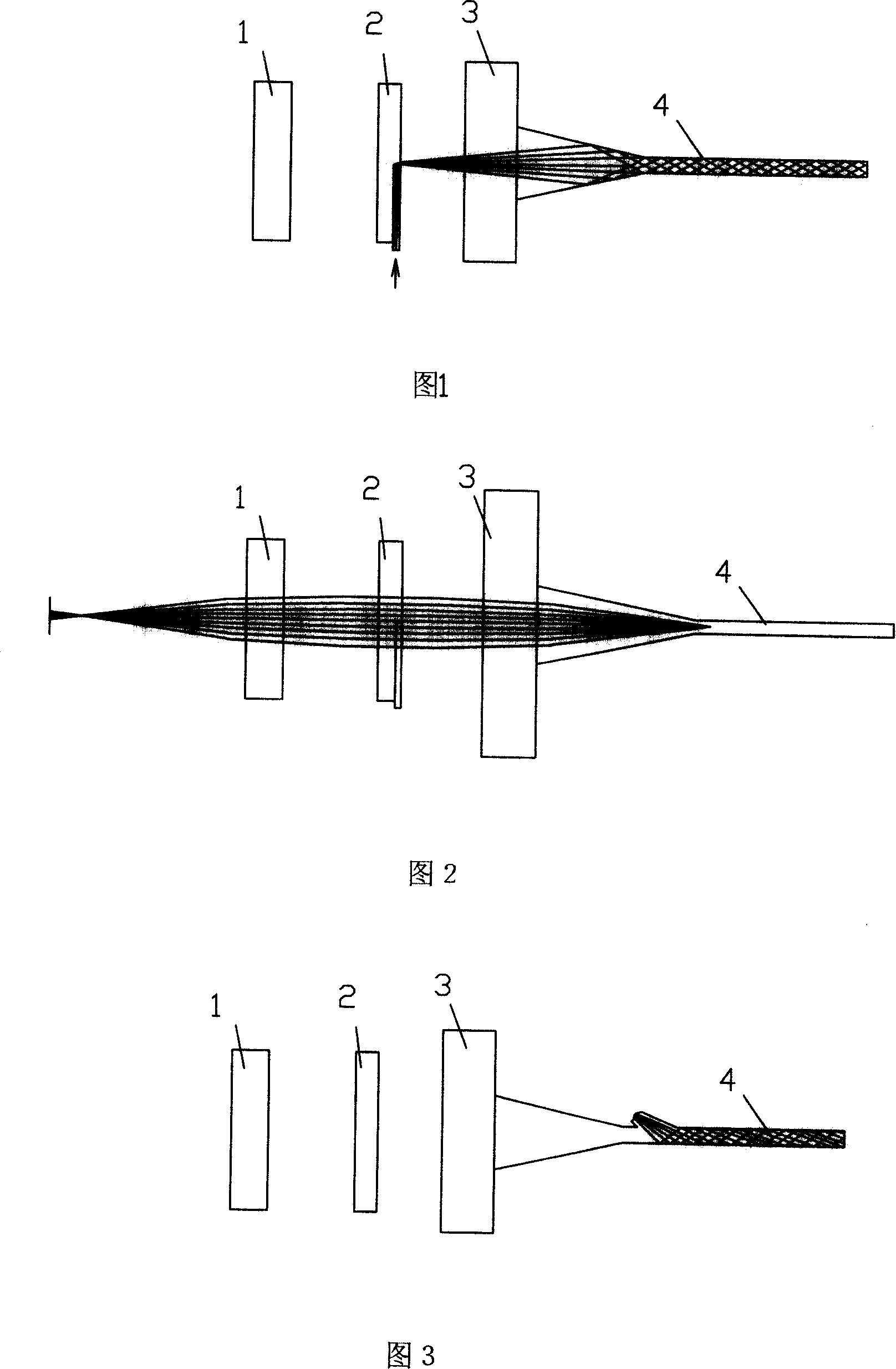
[0037]Embodiment 1, see Fig. 1-2. The thickness of the waveguide 4 in the sensing working area of ​​the present invention is about 30 μm, and the width of the waveguide in the vertical direction is large enough so that each slot can be considered as an anti-resonant planar waveguide. In the middle of the back of the sensor head is a conical microlens light-collecting area, so that the incident light enters the waveguide in the sensing area at an appropriate angle. The third part is an aspheric microlens 1, which is used to collect the fluorescent signal output from the sensing waveguide. Its working principle is as follows: a laser diode is used as a light source, and a self-focusing microlens is used to couple the laser beam into an anti-resonant planar waveguide. The 45° notch is plated with a reflective mirror to form a point light source on the axis of the molded waveguide. This injection of the laser beam at 90° to the axis makes the incident light and the fluorescent si...

Embodiment 2

[0040] Embodiment 2: The difference between this embodiment and Embodiment 1 is that the laser is coupled into the waveguide through a bypass, as shown in FIG. 3 .

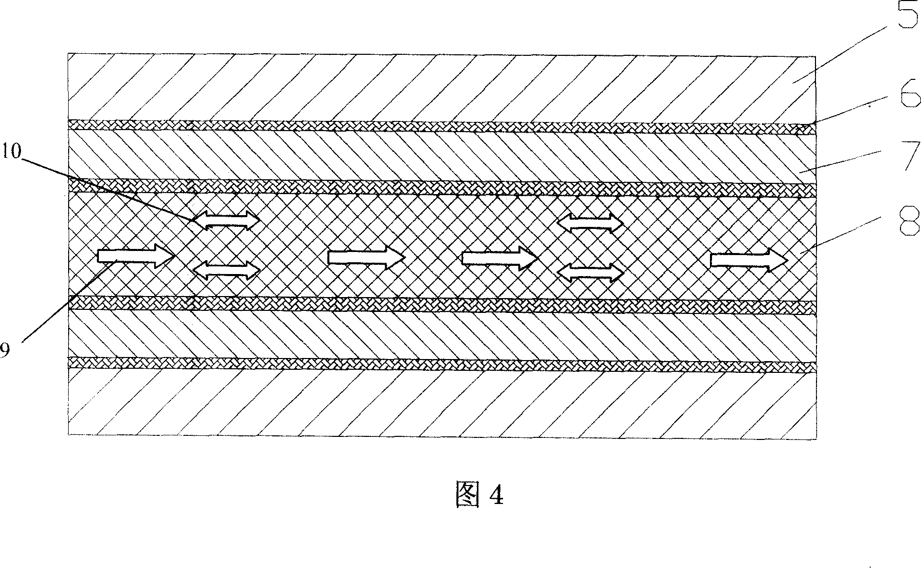
[0041] The solution of the substance to be tested in the present invention and the high and low optical materials together form an ARROW waveguide, as shown in FIG. 4 .


PUM


Abstract

This invention relates to one biological optical technique, which brings fluorescence label special antibody and test object mass in reverse vibration plane light wave guide lighting by laser through analysis fluorescence signals to judge whether there is antigen. This invention advantages are as: a, with more strong field inside wave guide field than outer one to trigger fluorescence intensity by more than ten times; b, avoiding couple consumption; c, connecting tens of thin tanks to realize rapid multi-channel test.

Description

technical field [0001] The invention relates to the field of optical technology, in particular to biochemical sensor technology. Background technique [0002] Since the 1970s, biomedical engineering has developed rapidly, and various biosensors for detecting chemical components in living organisms have emerged continuously. In the mid-1960s, enzyme sensors were first developed by using the catalysis of enzymes and its catalytic specificity, and reached the practical stage; in the 1970s, microbial sensors, immune sensors, etc. were developed; since the 1980s, the concept of biosensors has been obtained. It is recognized that as a branch of sensors, it is independent from chemical sensors and has been developed, which combines bioengineering and semiconductor technology and enters the era of bioelectronic sensors. At present, the combination of bioengineering technology and electronic technology, using the unique functions of organisms to manufacture various sensors similar t...

Claims


Application Information

Patent Timeline
IPC IPC(8): G01N21/64G01N33/53
Inventor 李坚谢康姜海明谢明杨华军
Owner 李坚
Why Eureka
Try Eureka