
Apparatus for controlling servopress and method for controlling the same

A technology of servo presses and control devices, which is applied to presses, stamping machines, manufacturing tools, etc., and can solve problems such as the difficulty in realizing high-speed slider drive and the inability to achieve high-production processing.

Inactive Publication Date: 2007-08-15
KOMATSU LTD +1
View PDF2 Cites 24 Cited by
  • Summary
  • Abstract
  • Description
  • Claims
  • Application Information

AI Technical Summary

Problems solved by technology

For this reason, there is a problem that it is difficult to increase the speed of the slider drive, and it is impossible to realize high-production processing.

Method used


Image

  • Apparatus for controlling servopress and method for controlling the same
  • Apparatus for controlling servopress and method for controlling the same
  • Apparatus for controlling servopress and method for controlling the same

Examples


no. 1 Embodiment approach

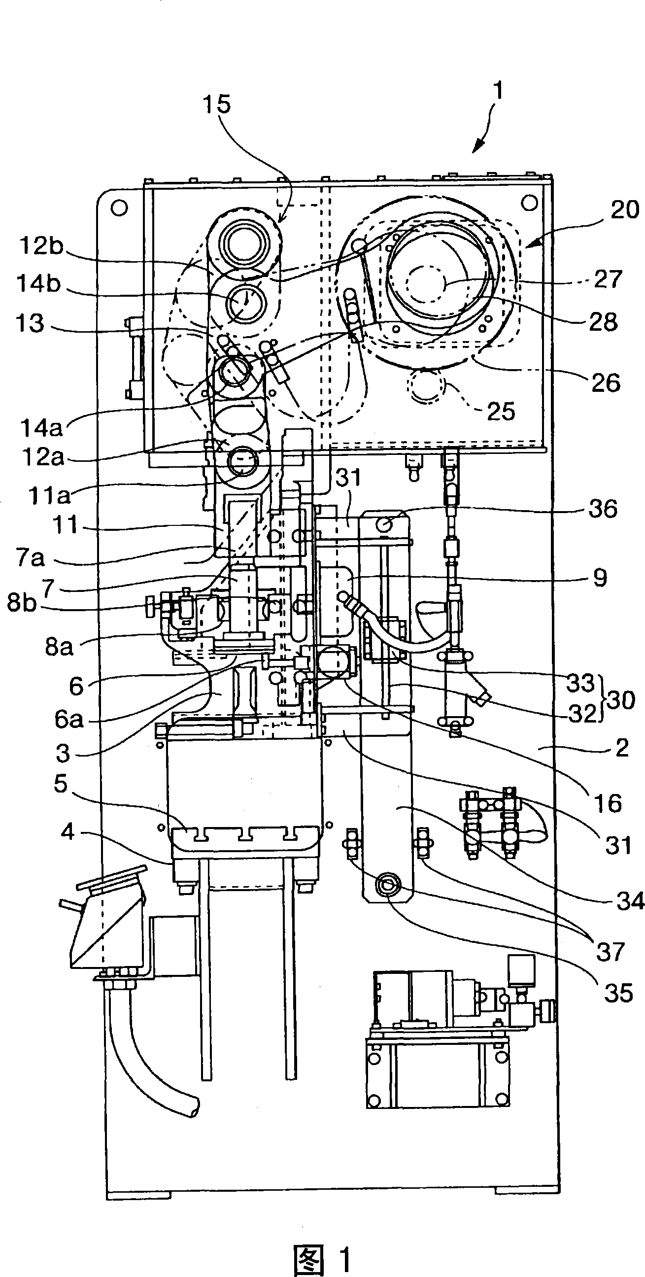
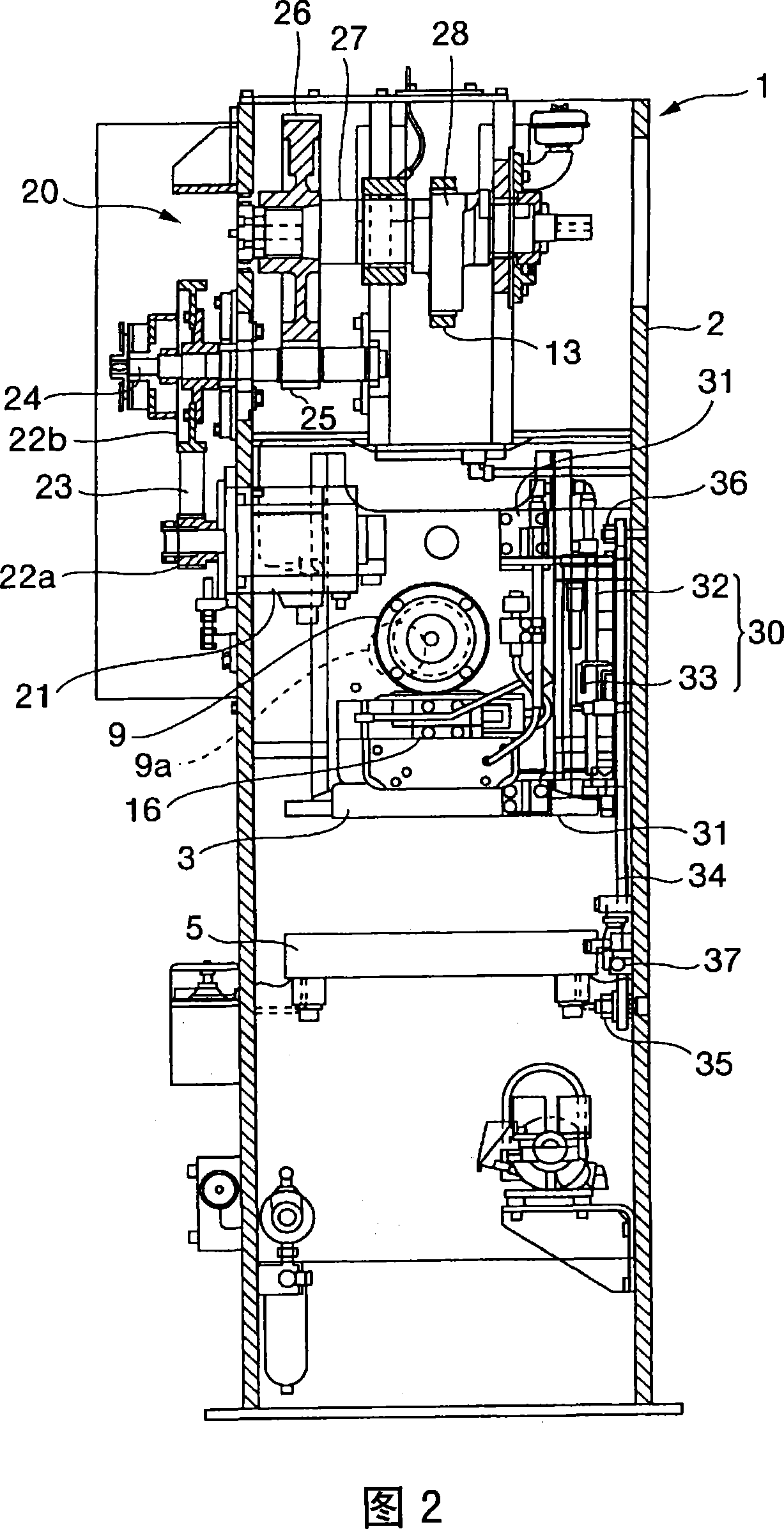
[0030] FIG. 1 shows a side partial sectional view of a servo press according to a first embodiment of the present invention, and FIG. 2 shows a rear partial sectional view of the same servo press.

[0031] In the servo press 1 according to the present embodiment, a slider 3 is vertically movably supported substantially at the center of the main body frame 2 . In addition, a base 4 is provided at the lower part of the main body frame 2, and a bolster 5 is attached to the base 4 to face the above-mentioned slider 3. As shown in FIG. Here, in the hole formed in the upper part of the slider 3, the body part of the threaded shaft 7 for adjusting the height of the die is rotatably inserted in a detached state. In addition, the threaded portion 7 a of the threaded shaft 7 is exposed upward from the slider 3 , and is screwed with an internal threaded portion formed at the lower portion of the plunger 11 provided above the threaded shaft 7 .

[0032] A worm wheel 8a is attached to the...

no. 2 Embodiment approach

[0067] Fig. 8 shows a schematic system configuration diagram of a servo press according to a second embodiment of the present invention. In addition, FIG. 9 shows an operation explanatory diagram (a) of a "rotation" figure and an operation explanatory diagram (b) of a "reverse" figure in the second embodiment, respectively. Also, the circle shown on the left side of each of Fig. 9 (a) and the same figure (b) represents the rotational movement of the gear 72 described later, and the rotation angle of the gear 72 corresponding to the top dead center is 0 degrees. The rotation angle of the gear 72 at the bottom dead center is 180 degrees. In addition, the time diagrams shown on the right side of each figure in Fig. 9 (a) and the same figure (b) show the change of the position of the slider along with the rotational movement of the gear 72, respectively, the horizontal axis represents the time, and the vertical axis represents the position of the slider. (high). In addition, in ...


PUM


Abstract

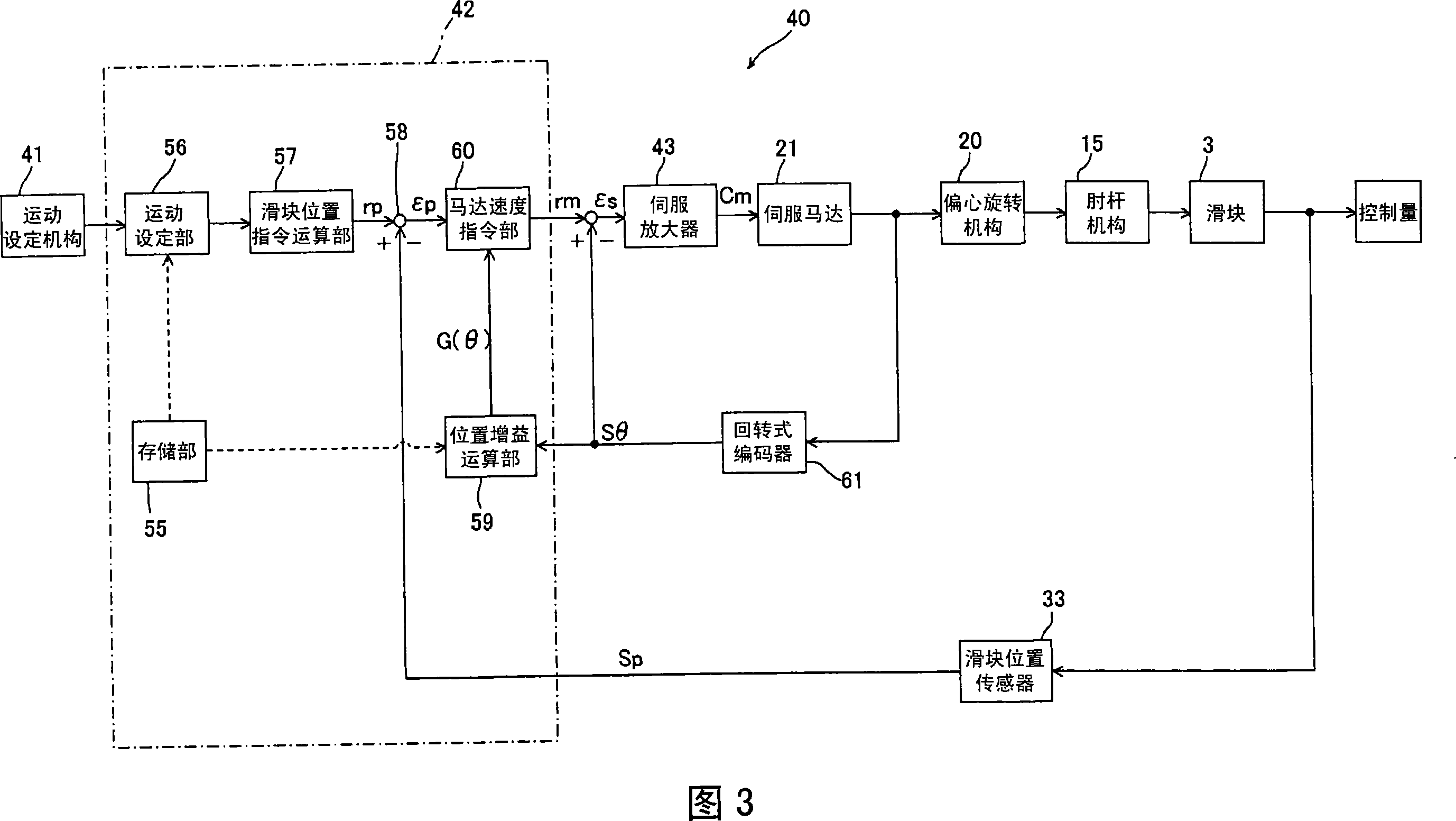
A control device and a control method for a servo-press capable of selectively performing high-production working and high-accuracy working by one pressing machine. The servo-press (1) is so formed that an eccentric rotary mechanism (20) is driven by a servo-motor (21), and the rotating power of the eccentric rotary mechanism (20) is transmitted to a slide (3) through a toggle link mechanism (15) to vertically drive the slide (3). The rotation of the servo-motor (21) is controlled by a motor speed instruction (rm) calculated based on a position gain (G (theta)) pre-set according to the position deviation (epsilon p) of the slide (3) and the speed ratio of the slide (3).

Description

technical field [0001] The present invention relates to a control device and a control method for a servo press machine in which the relationship between the rotation angle of a servo motor and the position of a slider is nonlinear, including an eccentric rotation mechanism and a link mechanism as a power transmission mechanism. Background technique [0002] Conventionally, there is known a servo press (for example, refer to Patent Document 1), which drives an eccentric rotating mechanism through a servo motor, and transmits the rotational power of the eccentric rotating mechanism to a slider through a toggle link mechanism to drive it up and down. The slide. According to this servo press machine, the slider can be driven up and down at high speed by the continuous rotation of the servo motor, so that high-production processing can be performed suitably. [0003] In addition, there is known a servo press (for example, refer to Patent Document 2), which converts the rotation...

Claims


Application Information

Patent Timeline
IPC IPC(8): B30B1/26B30B15/14B30B15/00
CPCB30B1/14B30B15/148
Inventor 铃木裕一畑幸男
Owner KOMATSU LTD
Learn More