Adjustable optical axis reflector box

An adjustable mirror technology, applied in the optical field, can solve the problems of high manufacturing cost, limited installation position, long optical path, etc., and achieve the effect of low production cost, convenient adjustment and fast adjustment

Inactive Publication Date: 2007-08-22
HENAN COSTAR GRP CO LTD
View PDF0 Cites 6 Cited by
  • Summary
  • Abstract
  • Description
  • Claims
  • Application Information

AI Technical Summary

Problems solved by technology

[0002] In the known technology, the optical signal incidence/reflection mirror box used for optical component coating monitoring is limited by its structural characteristics, so that there are many refraction and reflection paths of light beams in the mirror box, and the optical path is long, resulting in many optical devices and complex structures. high manufacturing cost
Secondly, because the exit and reflection angles of the optical axis are difficult to

Method used


Image

  • Adjustable optical axis reflector box

Examples


Embodiment Construction

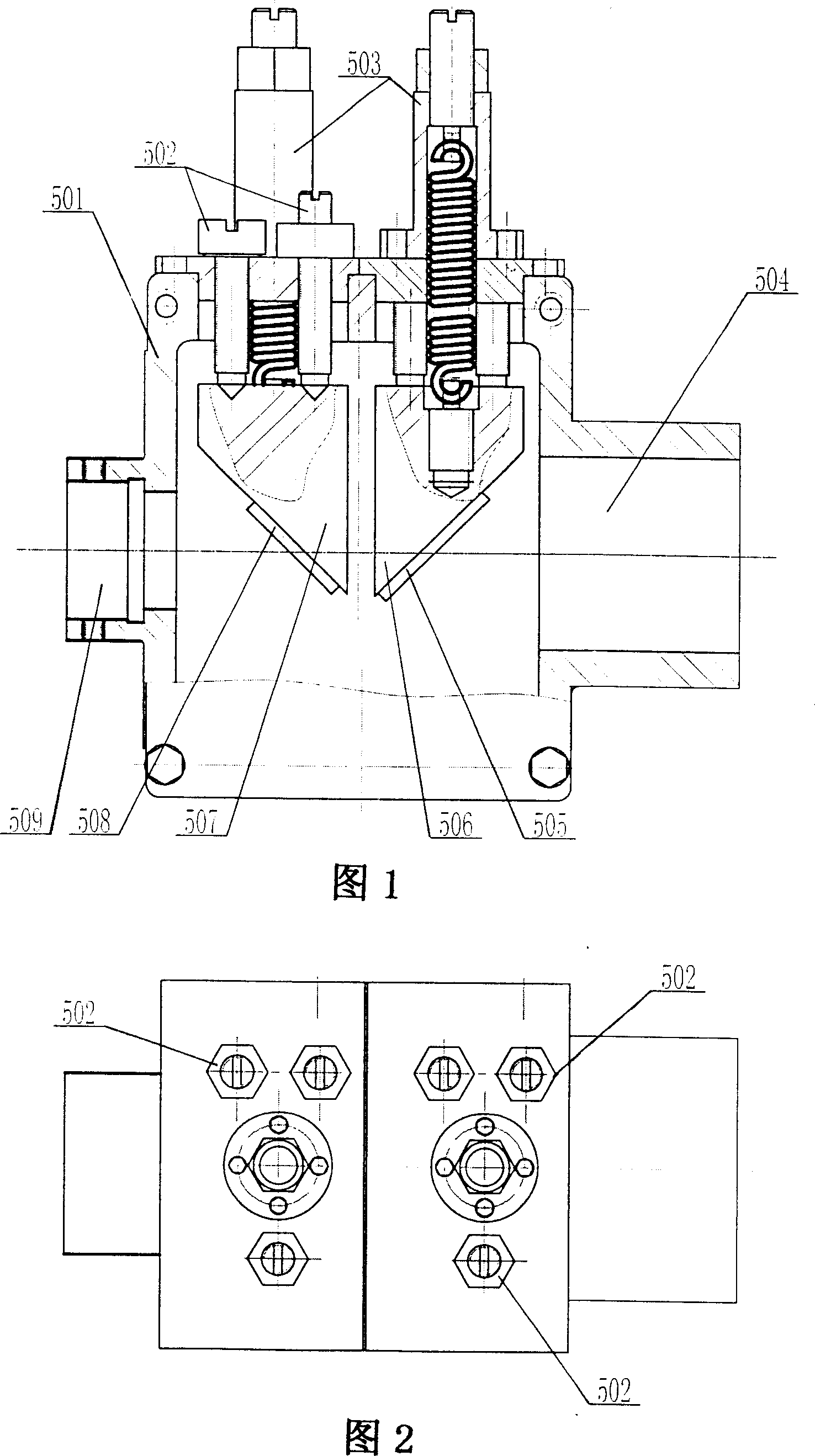
[0010] Referring to Fig. 1, Fig. 2, the adjustable optical axis reflector box of the present invention has a casing 501 with incident light through hole 509 and exit light through hole 504, and incident light through hole 509 and exit light through hole 509 and exit light in casing 501 A pair of optical surface incidence / reflection mirrors is arranged at the corresponding place of the through hole 504, wherein the light incidence mirror 508 is used to reflect the optical signal incident by the light projector outside the mirror box onto the coating comparison sheet to form an optical emission path for emitting the optical signal; The mirror 505 is used to reflect the optical signal projected on the coating comparison sheet to the light receiver outside the mirror box, forming an optical reflection path for outputting the reflected optical signal. What is connected with light incident mirror 508 is mirror holder 507, and the mirror holder that is connected with light reflection ...


PUM


Abstract

The invention relates to an adjustable optical axis reflector box for optical coating monitoring system, having a box body with light incoming through hole and light outgoing through hole, where a pair of optical plane incidence/reflection mirrors are arranged corresponding to the two through holes, a mirror seat is connected with the incidence/reflection mirror, the top of the mirror seat is equipped with an adjustment component extending out of the mirror box to adjust angle and height of the incidence/reflection mirror; by adjustment of the adjustment component, it can quickly adjust the height and angle of the incidence/reflection mirror and makes incident/reflected optical signal in the optical axis able to be accurately and stably projected to a light receiving surface, having advantages of simple structure, adjustment convenience, low cost, wide application range, etc.

Description

technical field [0001] The invention belongs to the field of optical technology, in particular to an adjustable optical axis mirror box for an optical coating monitoring system. Background technique [0002] In the known technology, the optical signal incidence / reflection mirror box used for optical component coating monitoring is limited by its structural characteristics, so that there are many refraction and reflection paths of light beams in the mirror box, and the optical path is long, resulting in many optical devices and complex structures. Manufacturing costs are high. Secondly, due to the difficulty in adjusting the exit and reflection angles of the optical axis, it cannot adapt to the projection of various optical signals at different distances, so the scope of application to the coating model is small, and the installation position is also greatly restricted. At the same time, it is very difficult to adjust during use, which is not only time-consuming and labor-in...

Claims


Application Information

Patent Timeline
IPC IPC(8): G02B1/10G02B7/182G02B7/198
Inventor 党亚军刘玲芳赵升林菊池和夫
Owner HENAN COSTAR GRP CO LTD
Why Eureka
Try Eureka