

Circular curtain camera system
A technology of camera system and ring screen, which is applied in the field of camera and can solve problems such as difficulty in fusion
- Summary
- Abstract
- Description
- Claims
- Application Information
AI Technical Summary
Problems solved by technology
Method used
Image

Examples
Embodiment 2
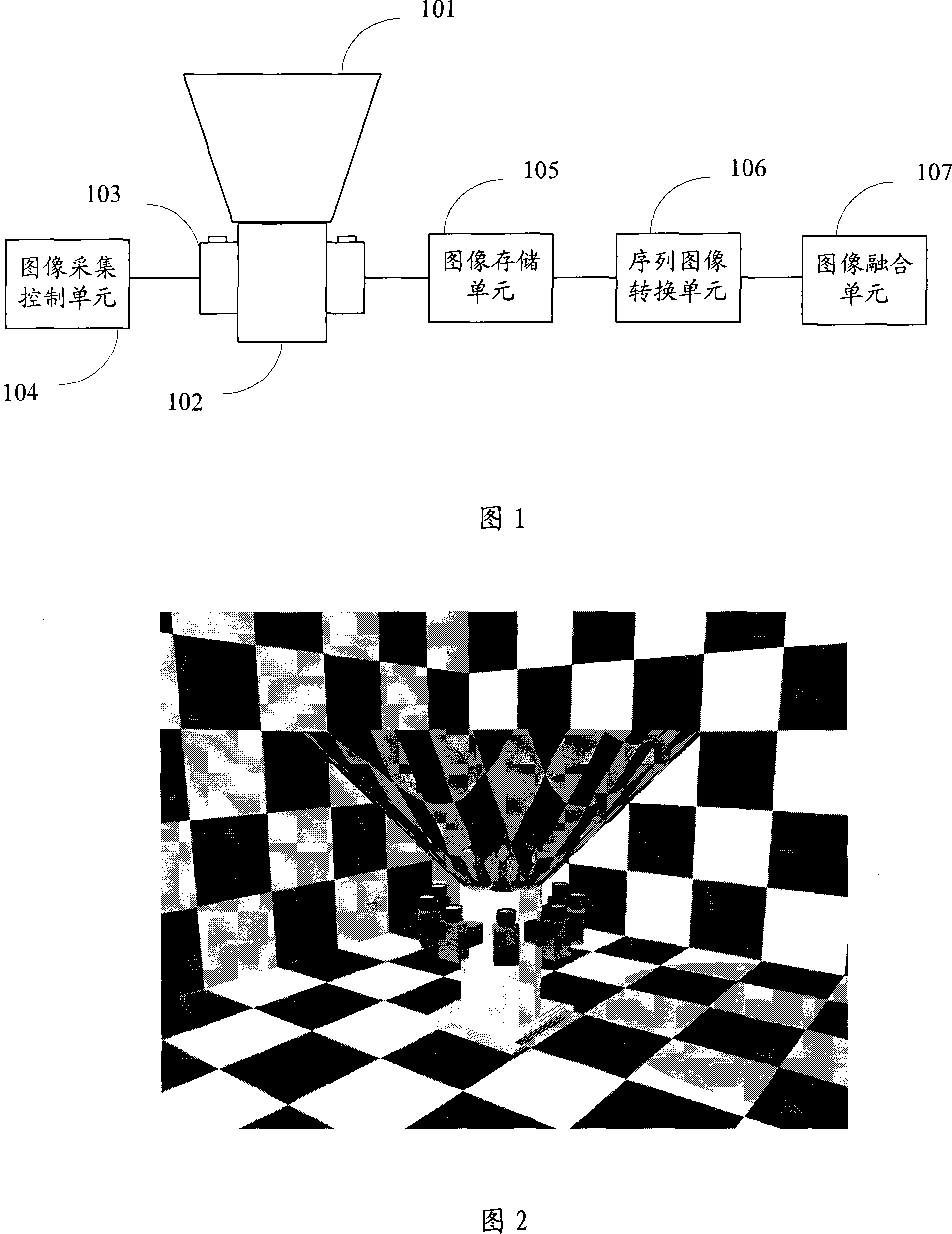
[0075] In general, since the screens of most ring-screen theaters are vertical, a vertical image is naturally needed to match it, so it is necessary to shoot a ring-screen image horizontally; therefore, in the embodiment shown in Figure 1, the camera Shooting vertically upwards, the shooting angle of the virtual image formed by the conical mirror is horizontal. In the foregoing description of the embodiment in FIG. 1 , it is also pointed out that the entire system shown in FIG. 1 can be rotated at a certain angle for shooting, so as to meet the need for oblique shooting in some special cases.
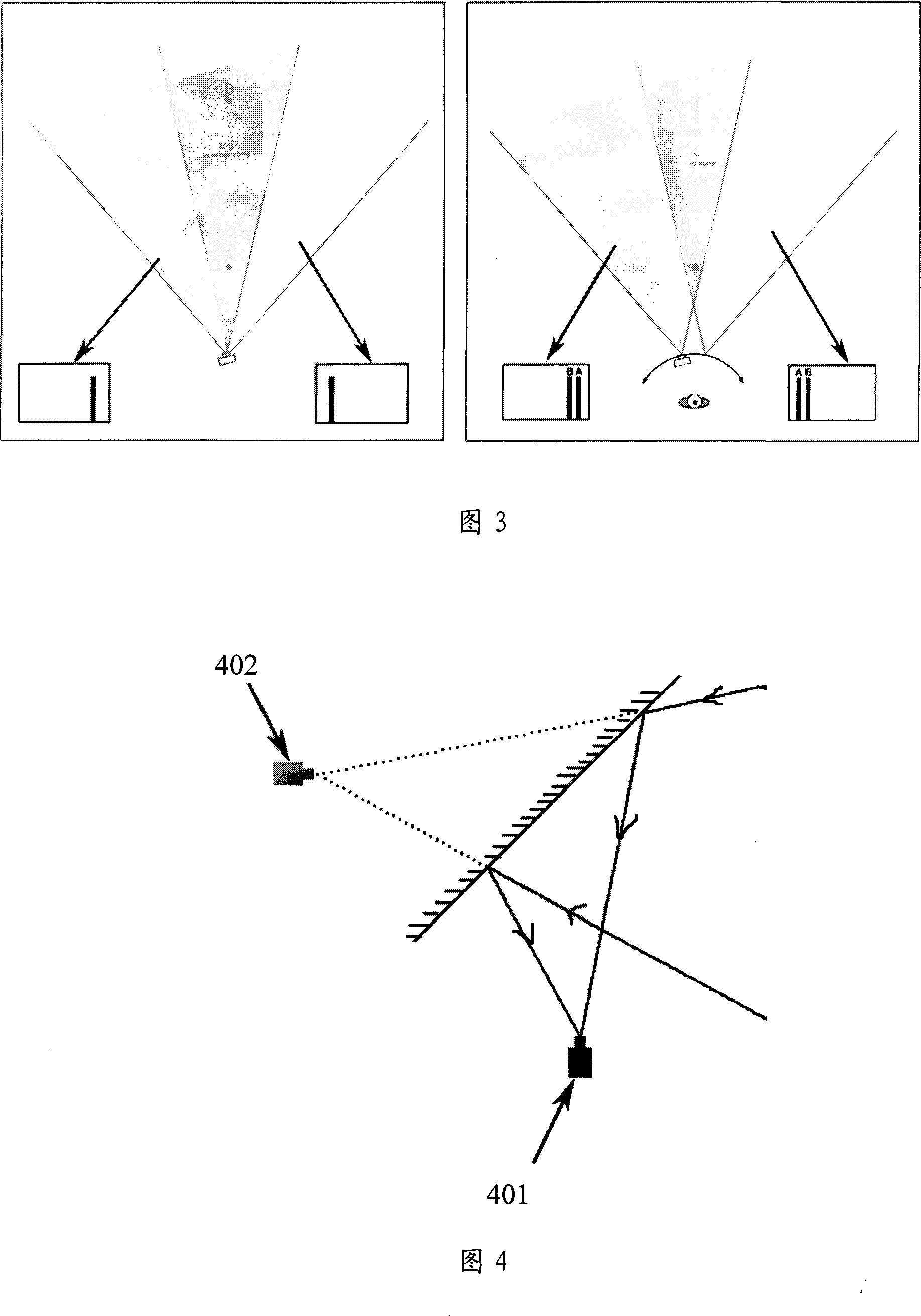
[0076] Embodiment 2 proposes another implementation scheme that meets the needs of special shooting angles of view. The main difference between it and the embodiment shown in FIG. If the shooting direction is parallel to the central axis of the conical mirror, but the shooting direction has a certain inclination angle, the virtual image obtained by the conical mirror is not horizontal, ...
Embodiment 3
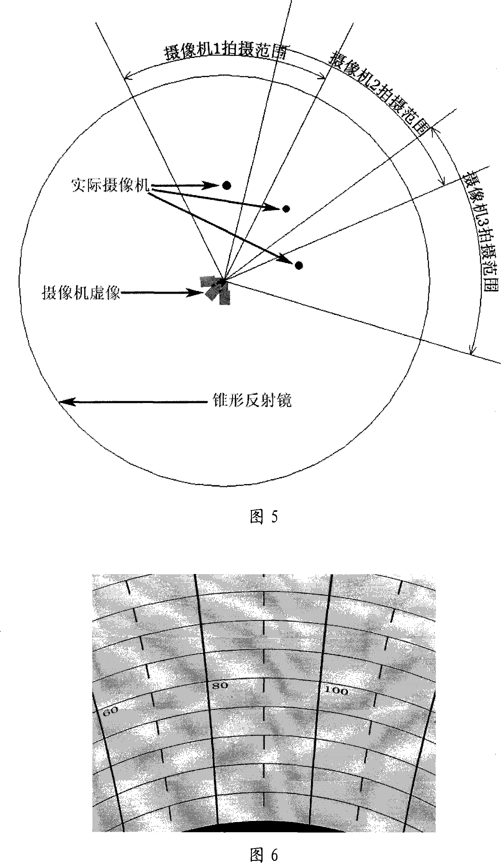
[0079] The conical mirror in the embodiment shown in Figure 1 is a positive conical mirror, and the cone angle is 90 degrees, and the conical reflector surface forms an angle of 45 degrees with the horizontal plane. The vertical viewing angle of the camera and the mirror size of the conical mirror. However, it is easy to know that the cone angle can be changed, but different angle changes will lead to different effects, and those skilled in the art can choose and apply according to needs. The following is a detailed description through the comparison of Fig. 10a, Fig. 10b, and Fig. 10c. For the convenience of comparison, the horizontal shooting of the virtual image is guaranteed in Fig. 10a, Fig. 10b and Fig. 10c.
[0080] In Fig. 10a, the conical mirror surface forms an angle of 60 degrees with the horizontal plane, that is, the cone angle is 60 degrees. In order to realize horizontal shooting, the shooting direction of the camera is adjusted and rotated to the right by a ce...
Embodiment 4
[0085] Through the introduction of Embodiment 3, it can be known that the cone angle of the conical reflector can be changed. The conical reflector of the embodiment shown in Figure 1 is a positive conical mirror, that is, the angles formed by the conical reflector surface and the horizontal plane in all directions are the same, and the cross section of the conical reflector is a circle. The biggest difference between Embodiment 4 and the embodiment shown in Figure 1 is that the angles formed by the conical mirror surface and the horizontal plane in each direction are not completely consistent, for example, the angles are changed between 30-60 degrees. , or vary between 42-48 degrees, that is, the cross-section in Example 4 is not a regular circle.
[0086] Since the cross-section in Embodiment 4 is not a regular circle, it is possible that the angles of the conical mirrors faced by each camera are different. From the introduction of Embodiment 3, it can be known that the cone...
PUM
| Property | Measurement | Unit |
|---|---|---|
| Cone angle | aaaaa | aaaaa |
Abstract
Description
Claims
Application Information