
Transformer structure

A transformer and iron core technology, applied in the field of transformer structure that can increase leakage inductance, can solve the problems of insufficient electrical safety distance of transformer structure, easy deterioration of tape, time-consuming and labor-intensive production, etc.

Active Publication Date: 2007-08-22
DELTA ELECTRONICS INC
View PDF0 Cites 6 Cited by
  • Summary
  • Abstract
  • Description
  • Claims
  • Application Information

AI Technical Summary

Problems solved by technology

[0010] The main purpose of the present invention is to provide a transformer structure, which separates the primary winding and the secondary winding by a spacer, or separates the primary winding and the secondary winding on different sides of the body. To increase the distance between the primary winding and the secondary winding to increase the leakage inductance of the transformer, and then adjust the leakage of the transformer by the distance between the protruding part of the U-shaped iron core and the I-shaped iron core In order to increase the electrical safety, and solve the problems in the prior art, the electrical safety distance of the transformer structure is insufficient, the production is time-consuming and laborious, and the tape is easy to deteriorate.

Method used


Image

  • Transformer structure
  • Transformer structure
  • Transformer structure

Examples


Embodiment Construction

[0055] Some typical embodiments embodying the features and advantages of the present invention will be described in detail in the ensuing description. It should be understood that the invention is capable of various changes in different forms without departing from the scope of the invention, and that the illustrations and diagrams are illustrative in nature and not limiting of the invention. .

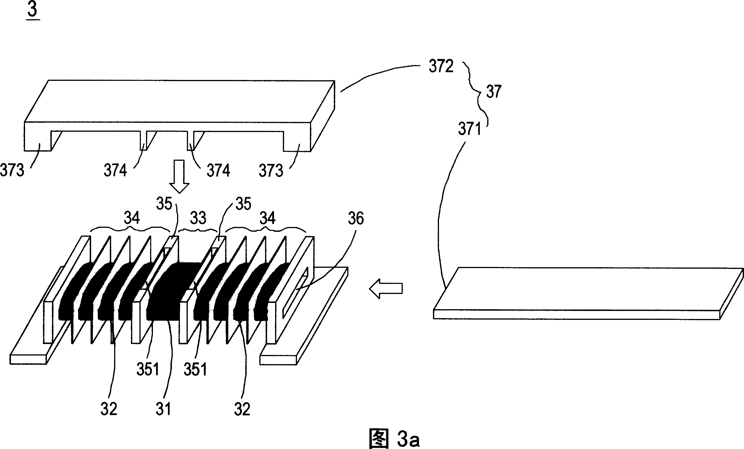
[0056] Please refer to Fig. 3 a, which is an exploded schematic view of the transformer structure of the first preferred embodiment of the present invention. As shown in Fig. 3 a, the transformer 3 includes a primary winding 31, a secondary winding 32, a first winding part 33, a Two winding parts 34, spacer plates 35, through parts 36 and core sets 37, wherein the first winding part 33 is used to wind the primary winding 31, and the second winding part 34 is used to wind the secondary Level winding 32, and arranged on both sides of the first winding part 33, the spacer plate 35 is a ...


PUM


Abstract

This invention relates to a transformer structure including: a primary winding, a secondary winding, a first winding part for winding the primary winding, a second winding part for winding the secondary winding, a spacing board set between the two winding parts and having a holding part, a through part passing through the first, the second parts and the spacing board, a iron core set including type-1 core and type-U core, multiple projection parts are set between two sides of type-U core, part of the 1-type core is set in the through part, the projection parts are plugged in the holding part of the spacing board to regulate the leakage inductance by the distance between the projection part and the 1-type core plugged in the through part.

Description

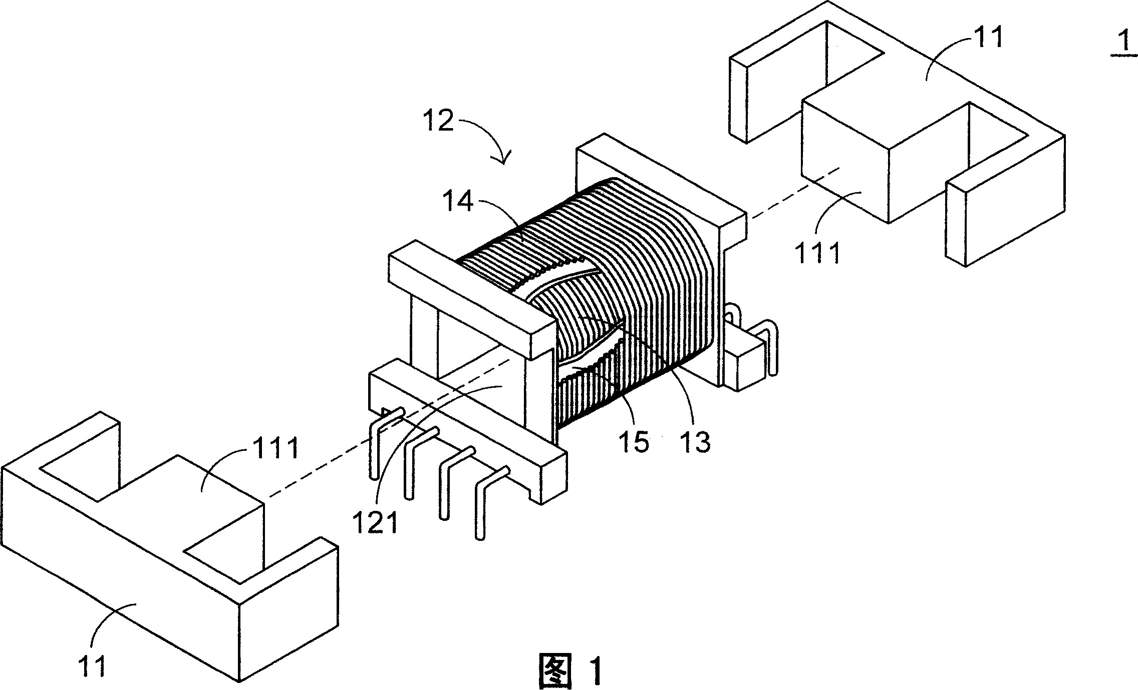
technical field [0001] The invention relates to a transformer structure, especially a transformer structure capable of increasing leakage inductance. Background technique [0002] Transformers are electronic components often used in various electrical equipment. Please refer to FIG. 1 , which is a schematic structural diagram of a conventional transformer. As shown in FIG. 1 , the transformer 1 mainly includes an iron core set 11 , a winding base 12 , a primary winding 13 , a secondary winding 14 and the like. Wherein, the primary winding 13 and the secondary winding 14 are wound up and down in the winding area of ​​the winding base 12 , and are insulated and separated from each other by an adhesive tape 15 . The core group 11 can set the axis 111 in the casing 121 of the winding base 12, so that the core group 11, the primary winding 13 and the secondary winding 14 generate electromagnetic coupling induction, so as to achieve the purpose of voltage conversion . [0003]...

Claims


Application Information

Patent Timeline
Patent Type & Authority Applications(China)
IPC IPC(8): H01F30/06H01F27/28H01F27/24
Inventor 张世贤
Owner DELTA ELECTRONICS INC
Learn More